 Free Shipping Over$200

- Products
- Marking
- Alternative

Analog Devices Inc./Maxim Integrated DS1135Z-25+T&R
- Part No.:
- DS1135Z-25+T&R
- Manufacturer:
- Analog Devices Inc./Maxim Integrated
- Category:
- Delay Lines
- Package:
- 8-SOIC (0.154", 3.90mm Width)
- Datasheet:
-
 DS1135Z-25+T&R.pdf
- Description:
- IC DELAY LINE 25NS 8SOIC
- Quantity:
Unit Price:$0.000000
Ext Price:$0.000000
- Payment:

- Shipping:

Inventory:0
Send us your inquiry,we will respond immediately.
In Stock : 0 PCS
| Qty. | Unit Price | Ext Price |
| 0+ | $0.000000 | $0.000000 |
*Products eligible for online ordering ship within 1-2 business days,please contact us for exact shipping times.
Also you can RFQ for DS1135Z-25+T&R or email to us: Email: [email protected] , we will contact you within 12 hours.
Product Details
DS1135Z-25+T&R - Maxim DS1135 3-in-1 Silicon Delay Line, 25 ns per Channel, SOIC-8 | DS1135
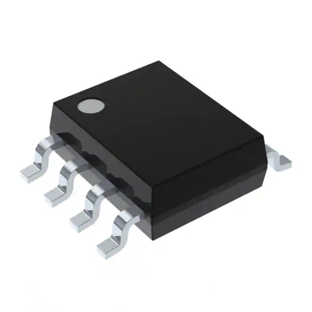
DS1135Z-25+T&R is the lead-free ("+"), tape-and-reel, 8-lead SOIC version of Maxim/Dallas' DS1135, a 3-in-1 all-silicon delay line with three independent buffered channels of 25 ns each. Each channel is a non-inverting buffer whose delay is set in silicon - ±1.5 ns accurate at 25°C and held stable over temperature and a 5 V ±5% supply - with both leading and trailing edges preserved, so input symmetry survives the delay. TTL/CMOS-compatible and able to drive 10 LS loads per output, it aligns clocks and signals in timing adjustment, clock-skew correction and bus synchronization - the recommended replacement for the DS1013/DS1035.
Product Introduction
The DS1135 treats time as a component: where digital designs once tuned delays with gate chains, RC networks or board-trace lengths, this all-silicon delay line packages three independent, factory-trimmed delays in one 8-pin device. Signal in, the same signal out - 25 ns later per channel in this -25 grade. DS1135Z-25+T&R is the lead-free SOIC-8 (150 mil) on tape and reel; the family spans 6 to 30 ns per step, and the DS1135L sibling serves 3.3 V systems.
What makes a silicon delay line worth a part number is the accuracy guarantee: ±1.5 ns initial tolerance for the 25 ns grade at 25°C/5 V, held to ±1.5 ns over 0°C to +70°C and ±2 ns across the full -40°C to +85°C industrial range. A chain of logic gates drifts with process, voltage and temperature; the DS1135's trimmed timing circuit does not. Equally important, delay accuracy applies to both edges, so a clock's duty cycle and a pulse's width pass through unchanged.
Interfacing is plain digital: TTL/LS-TTL and CMOS-compatible inputs (VIH 2.2 V / VIL 0.8 V), non-inverting buffered outputs that each drive up to 10 LS loads (IOL 12 mA), one +5 V supply at 35 mA max. Three channels in one package align three signal paths - clock to two data groups, three memory strobes, or cascaded for longer delays - replacing the older DS1013/DS1035 directly at higher speed grades.
Expert Technical Insight
Why buy delay as a component, and what should the designer check around a DS1135?
- Silicon beats gate chains for guaranteed time: a buffer chain's delay can vary 2:1 over process/voltage/temperature; the DS1135 is factory-trimmed to ±1.5 ns and characterized over the full range. When a setup/hold budget needs a known 25 ns, that guarantee is the product.
- Edge symmetry is part of the spec: both leading and trailing edges see the same accurate delay, so duty cycle survives - essential when delaying clocks rather than just pulses. Delay elements built from one-shot circuits do not promise this.
- Loading adds real time: outputs are characterized into 15 pF; heavy capacitive loads and long traces add delay beyond the trimmed value. Keep loads within the 10-LS rating, and budget the extra picoseconds-per-pF when the timing margin is tight. Need 3.3 V? Use the DS1135L; need adjustability? The DS1124 in our table is programmable.
Key Benefits
Three buffered channels in one SOIC-8, each delaying its input 25 ns - align a clock and two data groups with a single part.
Factory-trimmed all-silicon timing holds ±1.5 ns at 25°C and stays specified over temperature and 5 V ±5% - no RC drift, no gate-chain spread.
Leading and trailing edges carry the same accuracy, so duty cycle and pulse width pass through the delay unchanged.
Standard logic levels in, 12 mA IOL out per channel; 5 V supply, -40 to +85°C, drop-in upgrade for DS1013/DS1035.
Specifications
| Parameter | Value | Condition / Note |
|---|---|---|
| Device Type | 3-in-1 Silicon Delay Line | Three independent buffered delays |
| Manufacturer | Maxim (Dallas) | DS1135; replaces DS1013/DS1035 |
| Delay per Channel | 25 ns / 25 ns / 25 ns | -25 grade; family 6-30 ns |
| Initial Tolerance | ±1.5 ns | 25°C, 5 V (25/30 ns grades) |
| Over Temp/Voltage | ±1.5 ns / ±2 ns | 0-70°C / -40 to +85°C |
| Edge Accuracy | Leading and trailing | Input symmetry preserved |
| Supply Voltage | 5 V ±5% | 4.75-5.25 V; DS1135L = 3.3 V |
| Supply Current | 35 mA max | VCC = 5.25 V |
| Logic Compatibility | TTL/LS-TTL/CMOS | VIH 2.2 V / VIL 0.8 V |
| Output Drive | 10 LS loads | IOL 12 mA / IOH -1 mA; 15 pF test load |
| Polarity | Non-inverting | Buffered in and out |
| Operating Temperature | -40 to +85 °C | Industrial |
| Package | 8-Lead SOIC (150 mil) | Outline 21-0041 |
| Orderable Part Number | DS1135Z-25+T&R | SOIC-8, Pb-free, tape and reel |
Note: Values are taken from the Maxim DS1135 datasheet. Confirm every parameter against the latest official documentation before committing a design.
Package Information
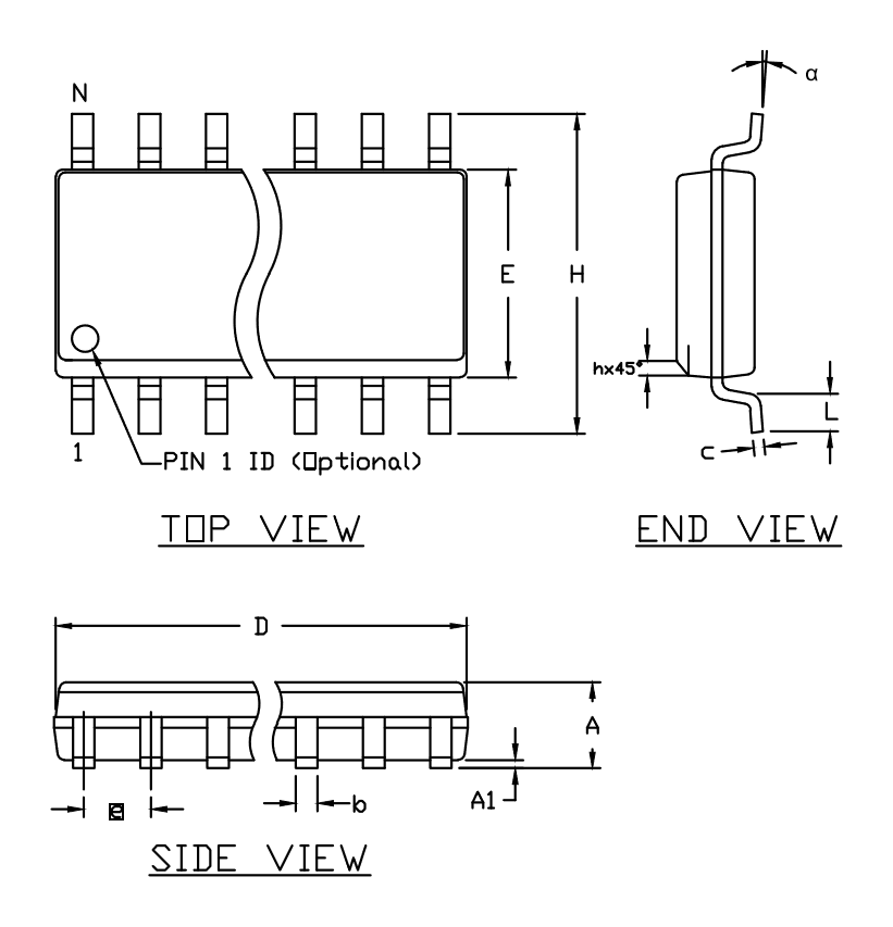
DS1135Z-25+T&R comes in the 8-lead, 150 mil SOIC (Maxim outline 21-0041, JEDEC MS-012 class, 1.27 mm pitch) - the "Z" in the part number. The "+" marks the lead-free finish and "T&R" the tape-and-reel packing; the device is vapor-phase, IR and wave solderable. Layout is simple logic practice: a 0.1 µF bypass at VCC, and remember that output trace capacitance adds to the delay - keep delayed-clock runs short and consistently loaded when channel-to-channel alignment matters. Package dimensions and pin-1 orientation are shown below.
📄 Full specifications are detailed in the official Maxim DS1135 datasheet.
Pin and Signal Definition
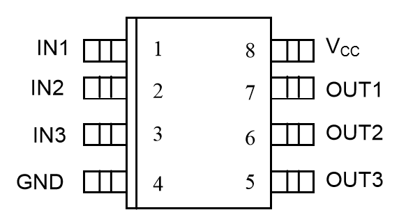
The 8-lead SOIC pairs the three inputs on the left with their outputs mirrored on the right:
- Pin 1 - IN1: Delay line 1 input (TTL/CMOS compatible).
- Pin 2 - IN2: Delay line 2 input.
- Pin 3 - IN3: Delay line 3 input.
- Pin 4 - GND: Ground.
- Pin 5 - OUT3: Delay line 3 output - IN3 delayed 25 ns, non-inverted.
- Pin 6 - OUT2: Delay line 2 output.
- Pin 7 - OUT1: Delay line 1 output.
- Pin 8 - VCC: +5 V supply; bypass with 0.1 µF at the pin.
Refer to the package drawing below for the physical pin numbering of the SOIC-8.
Alternative and Related Parts
The parts below are related silicon delay lines available in our catalog. They are not drop-in replacements; verify channel count, delay value/taps, supply voltage and package before substituting.
| Part Number | Brand | Type / Key Difference | Package | Note |
|---|---|---|---|---|
| DS1135LU-10 | Maxim | 3.3 V sibling, 10 ns per channel | µSOP-8 | Low-voltage systems |
| DS1035C-801 | Maxim | Predecessor 3-in-1 delay line | DIP-8 | DS1135 replaces it |
| DS1100LC-201/TR | Maxim | 5-tap delay line, 3.3 V | SOIC-8 | One input, five taps |
| DS1110E-100 | Maxim | 10-tap long delay line | SOIC-14 | Longer total delays |
| DS1124U-25+ | Maxim | 8-bit programmable delay | µSOP-8 | Adjustable in steps |
Selection Tips: Stay with the DS1135 for three fixed, matched delays on 5 V - pick the grade (6-30 ns) that fits the budget. The DS1135L serves 3.3 V rails; the DS1100/DS1110 give one signal multiple taps; the DS1124 makes the delay programmable; the DS1035 is the legacy part this one was designed to replace.
Manufacturer Information
Dallas Semiconductor built the silicon delay line category - timing sold as a trimmed, guaranteed component - and Maxim Integrated (which acquired Dallas in 2001, and itself became part of Analog Devices, Inc. in 2021) carried the DS-series timing parts forward. The DS1135 is the high-speed 3-in-1 member, the recommended replacement for the earlier DS1013/DS1035.
The combined ADI/Maxim catalog keeps the DS1135 documented with full datasheet characterization - delay tables per grade, tolerance over temperature and voltage, and edge-accuracy guarantees - the numbers a timing budget is signed off against.
Applications



Frequently Asked Questions
What is the DS1135Z-25+T&R?
It is Maxim/Dallas' 3-in-1 all-silicon delay line in an 8-lead SOIC: three independent non-inverting buffered channels, each delaying its input by 25 ns with ±1.5 ns accuracy, lead-free on tape and reel.
How accurate and stable is the delay?
The 25 ns grade is trimmed to ±1.5 ns at 25°C/5 V, holds ±1.5 ns over 0-70°C and ±2 ns over -40 to +85°C with a 5 V ±5% supply - and the accuracy applies to both leading and trailing edges, preserving duty cycle.
What logic can it interface with?
Inputs are TTL/LS-TTL and CMOS compatible (VIH 2.2 V, VIL 0.8 V); each buffered output drives up to 10 LS loads (12 mA IOL). The device runs from a single 5 V rail - for 3.3 V systems use the DS1135L sibling.
What other delay values exist in this family?
The DS1135Z family offers 6, 8, 10, 12, 15, 20, 25 and 30 ns per channel - all three channels share the same value within one part. Channels can also be cascaded for longer delays, and the DS1135 directly replaces the older DS1013/DS1035.
Disclaimer
Information Accuracy: The specifications on this page are based on the official Maxim DS1135 datasheet. We work to keep the information accurate and complete, but parameters can change with product revisions, so design engineers should verify all values against the latest official documentation before final design.
Product Authenticity Guarantee: All parts we supply are genuine factory originals with full material traceability.
Technical Support: Pre-sales and post-sales technical consultation is available free of charge.
Application Notice: This page is for reference only. Suitability for a specific application should be confirmed by the design engineer against the actual system requirements.
DS1135Z-25+T&R Specifications
- Specifications
- Attributes
- Property Value
- Manufacturer
- Analog Devices Inc./Maxim Integrated
- Series:
- -
- Package/Case:
- 8-SOIC (0.154", 3.90mm Width)
- Packaging:
- Tape & Reel (TR)
- Part Status:
- Active
- Number of Taps/Steps:
- -
- Function:
- Multiple, NonProgrammable
- Tap Increment:
- -
- Available Total Delays:
- 25ns
- Number of Independent Delays:
- 3
- Voltage - Supply:
- 4.75V ~ 5.25V
- Operating Temperature:
- -40°C ~ 85°C
- Delay to 1st Tap:
- 25ns
- Grade:
- -
- Qualification:
- -
- Mounting Style:
- Surface Mount
- Supplier Device Package:
- 8-SOIC
- Category:
- Delay Lines
DS1135Z-25+T&R Relevant information
- DS1135Z-25+T&R Tags
- Popular Search
The following parts are popular search parts in Delay Lines.
The Posts
-
LTM4680IY#PBF ADI DC DC Converter Selection Guide
LTM4680IY#PBF from ADI: applications, datasheet checks, pinout notes, alternatives, replacement risks and sourcing checks for engineers and buyers.

-
LTM4622IY#PBF ADI DC DC Converter Selection Guide
LTM4622IY#PBF from ADI: applications, datasheet checks, pinout notes, alternatives, replacement risks and sourcing checks for engineers and buyers.
-
HMC349AMS8GETR ADI RF Switch Selection Guide
HMC349AMS8GETR from ADI: applications, datasheet checks, pinout notes, alternatives, replacement risks and sourcing checks for engineers and buyers.
-
HMC284AMS8GETR ADI RF Switch Selection Guide
HMC284AMS8GETR from ADI: applications, datasheet checks, pinout notes, alternatives, replacement risks and sourcing checks for engineers and buyers.
-
ADSP-2185LBSTZ-210 ADI DSP Selection Guide
ADSP-2185LBSTZ-210 from ADI: applications, datasheet checks, pinout notes, alternatives, replacement risks and sourcing checks for engineers and buyers.
-
ADSP-21489BSWZ-4A ADI DSP Selection Guide
ADSP-21489BSWZ-4A from ADI: applications, datasheet checks, pinout notes, alternatives, replacement risks and sourcing checks for engineers and buyers.
-
ADL5565ACPZ-R7 ADI Special Purpose Amplifier Selection Guide
ADL5565ACPZ-R7 from ADI: applications, datasheet checks, pinout notes, alternatives, replacement risks and sourcing checks for engineers and buyers.
-
ADL5561ACPZ-R7 ADI Special Purpose Amplifier Selection Guide
ADL5561ACPZ-R7 from ADI: applications, datasheet checks, pinout notes, alternatives, replacement risks and sourcing checks for engineers and buyers.
Related Products
-
DS1135Z-20+T&R
Analog Devices Inc./Maxim Integrated
-
DS1135Z-10+T&R
Analog Devices Inc./Maxim Integrated
-
DS1135Z-15+T&R
Analog Devices Inc./Maxim Integrated
-
DS1135Z-10/T&R
Analog Devices Inc./Maxim Integrated
-
DS1135Z-6+T&R
Analog Devices Inc./Maxim Integrated
-
DS1135Z-8+T&R
Analog Devices Inc./Maxim Integrated
-
DS1135U-10+T&R
Analog Devices Inc./Maxim Integrated
-
DS1135U-15+T&R
Analog Devices Inc./Maxim Integrated
-
DS1135U-20+T&R
Analog Devices Inc./Maxim Integrated
-
DS1135LU-10+T&R
Analog Devices Inc./Maxim Integrated
-
DS1135LU-12+T&R
Analog Devices Inc./Maxim Integrated
-
DS1135LU-15+T&R
Analog Devices Inc./Maxim Integrated


