- Products
- Marking
- Alternative
AT24C256 Keeping Calibration and Parameters on an Edge Device
AT24C256 Keeping Calibration and Parameters on an Edge Device
A calibrated edge device often fails in a quiet place: a few bytes of parameters no one treated as a product file. The processor may boot, the sensor may answer, and the model may run, yet the device can still report the wrong pressure offset, threshold, motor zero point or radio trim because its small nonvolatile parameter store was handled like spare memory. AT24C256 belongs in this review as a 256-Kbit I2C serial EEPROM used for calibration constants, configuration records and service state that need to survive power loss.
Microchip identifies AT24C256C as an I2C-compatible two-wire serial EEPROM with 256 Kbits arranged as 32,768 x 8. The data sheet also describes I2C Standard, Fast and Fast Mode Plus operation across stated supply ranges, write-protect behavior and page-write operation. Those facts are enough to set the engineering frame: this is not bulk model storage or executable code storage. It is a small, byte-addressed memory that deserves a storage map, write policy and substitution test.
Start with the Parameters That Change the Product
Calibration data can be small and still decide the product. A load cell offset, a temperature slope, a microphone gain trim, a motor angle zero point, a field threshold, a serial number block or a radio region setting may occupy only a few bytes. Those bytes can change the behavior more than a large firmware image does. The first selection step is to write down which records are factory-set, which are field-updated, which are user settings and which are read-only identity values.
AT24C256 gives enough space for many small records, but space alone does not create a safe parameter store. Each record needs an address, length, version rule, default value, integrity check and ownership rule. If the firmware team, factory fixture and service tool each write their own format, the memory becomes a shared scratchpad. That is how a device passes early tests and then fails after a service update or firmware revision.
A good map separates factory calibration from field settings. Factory calibration should change rarely and often needs tighter write control. Field settings may change through the application. Temporary counters or logs may need a different storage device if they write often. Treating all records as equal can wear the wrong region, erase the wrong meaning or make a returned unit hard to diagnose.
Use EEPROM for Small Persistent State, Not for the Job of Flash
Previous memory articles in this group dealt with boot images, model files and code paths. EEPROM plays another role. It stores values that the device reads to decide how its hardware should be interpreted. The file is usually small, but the consequences are direct. A wrong accelerometer bias can move the measured pose. A wrong current-sense gain can move a power decision. A wrong motor zero point can move the mechanical system.
That difference changes the writing style of the firmware. Large Flash updates may be planned as image swaps. EEPROM updates are often small commits. A single parameter record may need two copies, a sequence count and a checksum so a power cut cannot leave the device with a half-written value that looks valid. The memory part should be selected with that commit method in mind.
Do not use the EEPROM as a casual log sink. A calibration store may support many writes, but repeated status logging, high-rate event counters or model telemetry belong in a design review of write endurance and data volume. If the product needs frequent logging, use a region and medium designed for that load, or change the logging strategy before the board ships.
Plan the I2C Bus Before Treating the Part as Simple
I2C looks easy because it has two signal lines, SCL and SDA. On a real edge device, the bus may also carry sensors, expanders, power monitors, secure elements or another EEPROM. Pull-up values, bus capacitance, cable stubs, voltage translation, address pins and firmware arbitration all affect whether the parameter store is reliable. A memory device can be correct and still live on a weak bus.
Place the EEPROM close enough to the controller that the bus stays clean, or prove the bus margin if the device sits near a sensor module connector. Choose pull-ups based on bus voltage, edge rate, device count and power budget. If the bus crosses a connector, test unplugged states, hot insertion risk and ESD exposure. If the bus uses level shifting, test the EEPROM at the lowest rail and slowest edge expected in the product.
Address planning matters as soon as more than one I2C device is present. AT24C256-family parts use address pins in typical designs, but exact package and suffix choices decide how those pins are bonded and used. A second source can change address behavior, write-protect handling or package pinout. The review should name the final address, pull choices and bus scan expectation.
Write Protection Is a Product Policy
The write-protect input is an electrical pin with product policy behind it. It decides which data may change, when it may change and which tool is trusted to change it. Factory calibration may be written once and locked by hardware. User settings may stay writable through firmware. A service counter may be writable under controlled service mode. Mixing those policies on one memory device is possible, but the hardware and firmware have to agree.
Decide how the write-protect net is driven before layout. If it is tied to a fixed level, the product gives up some service flexibility. If firmware controls it, a software defect can open a region that should have stayed protected. If a fixture controls it through a pad, the board needs a clear access point and a rule for production state after programming. None of these choices is universal. The point is to choose one deliberately.
For field updates, use a commit method that can recover after a power cut. A common pattern is two records with sequence counters and checksums. The device reads the newest valid record and ignores incomplete writes. That pattern costs bytes, but it turns a small EEPROM into a controlled state store rather than a fragile byte bucket.
Page Writes Need Record Boundaries
AT24C256C data sheet material describes page-write operation, and page boundaries deserve attention even when the records are small. If firmware writes across a boundary without understanding wrap or page behavior, the stored data can land somewhere else than expected. A driver that works for byte writes can still be wrong when the factory fixture switches to larger page writes for speed.
Record layout should respect page size and update order. Keep a record header, payload and check value in a region that the driver writes predictably. If a record is larger than a page, test both the normal write and an interrupted write at every boundary. If the product uses partial page writes, document that behavior in the driver review and in the fixture notes.
The firmware should also avoid unnecessary rewrites. Before writing a record, compare whether the value changed. Batch related settings when the product can tolerate it. Keep high-churn counters away from factory calibration records. Small changes in software policy can extend margin without changing the part.
Factory Calibration Needs Traceability
Calibration is only useful if the product can prove which values were written. A factory fixture should identify the board, measure the hardware, calculate the record, write it, read it back and store the result. The record should carry a version or type field so later firmware can reject formats it does not understand. A returned unit should tell engineering whether the failure came from the sensor, the calibration value, the read path or the algorithm.
Traceability does not require a large database in the EEPROM. It requires a clear record identity. The external production system can hold detailed measurement data, while the EEPROM holds the values the device needs to run. If the device stores both calibration and a board identity block, keep the identity block read-only after factory programming or protect it through the chosen write-protect method.
Service flow also needs planning. If a field repair replaces a sensor board, can the EEPROM move with the calibrated assembly, or must the new assembly be recalibrated? If calibration belongs to the sensor module, putting the EEPROM on that module may be cleaner than storing values on the main controller board. If calibration belongs to the full unit, the storage location should match that ownership.
Substitution Requires More Than Capacity and Pins
EEPROM alternates can look interchangeable: same density, same I2C bus, same 8-pin outline. The details still matter. Voltage range, speed grade, page size, address pins, write-protect polarity, write cycle timing, endurance rating, retention rating, package height and bus input behavior can affect the product. A replacement that reads correctly once may still fail during fast fixture programming or low-voltage startup.
Qualify alternates with product records, not with an empty read-write loop. Test factory programming, power loss during write, checksum rejection, normal boot, low-voltage start, bus sharing, write-protect behavior and service recovery. If the product has a sleep mode, test wake and parameter read after the real rail sequence. If the EEPROM is on a module connector, test contact noise and reset timing.
Keep the approved list by exact orderable part and package. Do not approve a vague AT24C256 label and let purchasing choose any clone. For small memories, a small package difference or address-pin difference can create a production issue that costs more than the memory itself.
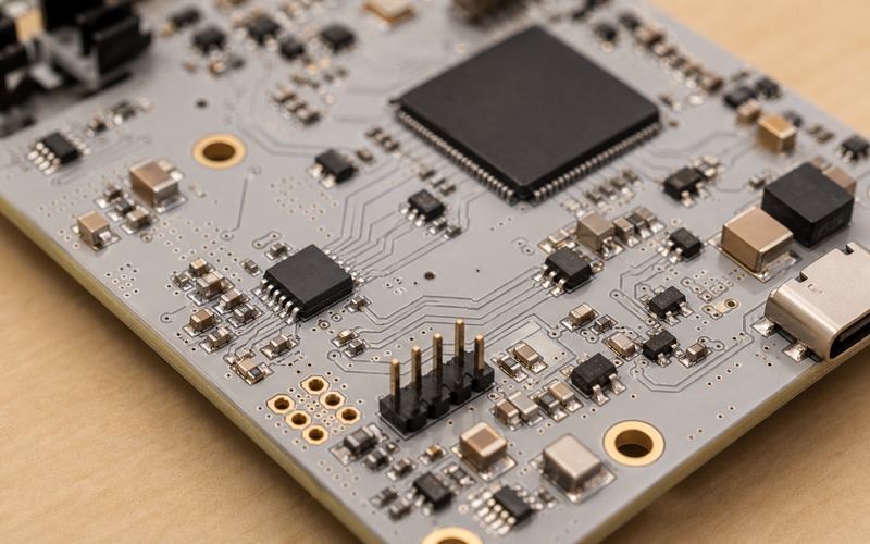
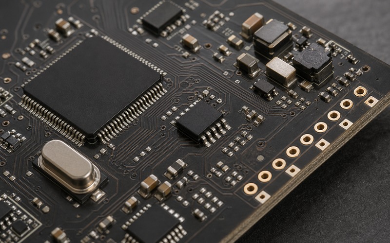
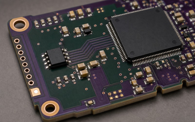
Layout Should Make the Parameter Store Inspectable
The image for this article places the EEPROM near the controller, pull-ups, decoupling and test pads because those details are visible decisions. SCL and SDA should have clean routes, the pull-ups should match the bus plan, the decoupling capacitor should sit near the supply pin, and the write-protect path should be understandable from the schematic to the board. A mystery net on WP or a hidden pull-up value creates avoidable debug time.
Board-edge pads help when a unit will not boot because of bad parameters. A service tool can read the EEPROM, compare records and recover without running the main application. If direct access is not provided, firmware must expose a recovery path that works even when the parameter record is damaged. One of those paths should exist before production.
Inspection access should respect manufacturing. Pads need enough clearance for probes, no conflicting tall parts and a finish that handles the planned contact. If the product is sealed, decide whether the pads are for factory use only or service access as well. The decision changes enclosure and process design.
Final AT24C256 Selection Checklist
Before approving AT24C256 for calibration and parameter storage, confirm the exact suffix, voltage range, package, I2C speed, address pins, pull-up values, bus capacitance, write-protect policy, page-write behavior, record map, checksum rule, commit method, factory fixture flow, read-back rule, service recovery path, write-frequency estimate and approved alternate test.
The part is a good fit when parameter ownership is clear, the write policy protects factory data, the bus has margin, the record map survives interrupted writes and each alternate passes the same product-level tests. It is a weak fit when the memory is approved as generic I2C storage and the calibration format is left for the last firmware week.
Related information
- 2026.07.01 IS25LP128 as Code Storage for Edge AI
- 2026.07.01 MT25QL128 Feeding Weights Over QSPI