- Products
- Marking
- Alternative
MT25QL128 Feeding Weights Over QSPI
MT25QL128 Feeding Weights Over QSPI
Weights stored in serial NOR flash do not feed an inference engine by magic. They cross a narrow controller path, move through cache or RAM, and reach the compute block only as fast as the board, firmware and memory map allow. MT25QL128 belongs in that discussion because it sits in the class of Micron serial NOR parts used when an edge device needs nonvolatile storage without a wide parallel bus.
Micron's public product page for MT25QL128ABA8E12-0SIT identifies it as a 128Mb, 3V multiple I/O serial NOR Flash device. That line tells the buyer the broad family, density and voltage class. It does not answer the harder design question: can this memory path deliver a model, a table of weights or a firmware partition at the time the application needs it?
Start with the Weight Path
The first review is the path from stored model to running inference. A small device may copy the full model from MT25QL128 into SRAM during startup, then run only from fast local memory. A larger design may copy sections of a model into external RAM. Another product may leave some tables in flash and read them during the job. Those choices place different pressure on QSPI bandwidth, latency and firmware control.
Write the path as a sequence. Power rises, the host configures the serial NOR mode, the firmware finds a model header, validates the file, reads the weight data, places it in the execution memory or a buffer, then starts the compute block. If any step is vague, the memory part is being approved before the system knows how it will be used.
Model storage is also a partitioning problem. A 128Mb class device gives about 16 MB raw capacity before headers, metadata, rollback space, firmware reserve and alignment are counted. A compressed model file that fits in a folder may fail the board plan after those regions are added.
QSPI Is a System Feature
QSPI is often treated as a flash feature, yet the final behavior comes from the host controller, board routing, command mode, cache, driver and boot code. MT25QL128 can support multiple I/O serial operation in the right setup, but the product still has to prove the exact controller mode used by the chosen processor. A line item saying serial NOR flash is not a performance signoff.
Check the controller against the memory command set used in production. Single SPI, Dual SPI, Quad SPI, memory mapped read, read command opcode, address length, dummy cycles, mode bits and status register setup can all change the result. A part may read correctly through a programmer and still run slowly or fail under the target boot ROM if the ROM expects a different setting.
QSPI also needs a timing budget that looks like the final product. The trace length is short in many layouts, but the clock edge, return path, supply noise and host pin configuration still matter. The board should be tested with final firmware, final regulator ramp and final low-power wake path, rather than a debug script on an open bench.
Decide Whether to Stream, Copy or Map
There are three common ways to use a serial NOR part in an edge inference design. The firmware can copy the model into RAM before inference. It can map flash into the processor address space and rely on cache. It can stream blocks of weight data into a buffer as each layer or task needs them. Each method creates a different failure shape.
Copying into RAM gives a cleaner run once the copy is done, but startup time, RAM size and power interruption during the transfer must be checked. Mapping through a controller can save RAM, but cache misses and random access patterns can expose the narrow serial path. Streaming can fit a larger model into a smaller device, but the model layout, buffering and scheduler have to be designed around the flash read behavior.
The layout of the model file should match the chosen method. Sequential reads are friendlier to a serial flash path than scattered reads. Reordering weights, packing lookup tables, aligning sections and keeping frequently used data in faster memory can change the user-visible response more than the flash density does.
Capacity Approval Needs the Real Image
A part can have enough density on paper and still leave no room for the real release image. The model may need a header, version field, checksum, signature, calibration block, preprocessing table, quantization table, fallback model or test vector. The application may also need a boot image and a recovery image in the same flash. That plan should be drawn before the part is purchased.
Keep the model file, firmware image and storage map tied together. If the model is updated without the matching preprocessing code, the flash can contain valid bytes that create invalid results. If the firmware is updated without the matching model version, the application may load a file that passes a checksum but no longer matches the tensor layout.
Capacity signoff should use the largest planned release, margin for metadata and at least one realistic update case. A design that leaves no spare erase block for field update or recovery can pass early testing and then become hard to maintain.
Read Performance Is More Than Clock Rate
Clock frequency is only part of serial flash throughput. Command overhead, address phase, dummy cycles, bus width, controller FIFO, cache line size, driver overhead and read pattern all contribute. A benchmark that copies one large continuous file may look fine while layer-by-layer access stalls during a real inference job.
Measure with the real access pattern. If the inference code loads full weight sections one after another, test that. If it jumps between tables, test the jumps. If it wakes, reads a compact model section and sleeps again, test the wake path. The correct number for the review is the time spent from request to usable data, not the headline serial clock.
When timing margin is tight, look at the whole chain. Faster flash may help, but so can a different model layout, a preload step, a larger buffer, a controller cache setting or moving high-use constants into internal memory. The memory part is one lever in a path that includes firmware and architecture.
Protect the Model as a Product File
Weights are product data. They should be treated with the same release discipline as firmware. The file needs identity, length, version, integrity check and a rule for rejection. The product should know whether it can boot with an older model, whether firmware can refuse an incompatible model, and how recovery works after a failed update.
For devices that accept field updates, decide where the new model lands before it becomes active. Many teams write into inactive space, verify the file, then switch a small state value. If the density does not leave room for that process, the update strategy must change before production.
Security choices depend on the product. A medical, access control or metering device may need stronger signing and anti-rollback behavior than a small lab instrument. The flash selection cannot define that policy, but it has to leave space and access behavior for the policy the system chooses.
Layout and Decoupling Set the Reading Margin
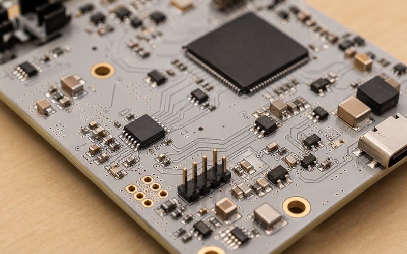
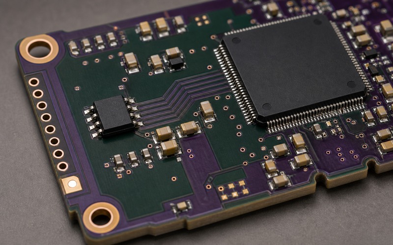
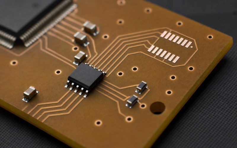
The serial flash should sit near the host that reads it. Clock, chip select and data lines should have short, clear routes, an uninterrupted return path and local decoupling close to the supply pins. The QSPI bundle in the board view is intentionally short because long routes around connectors, power inductors or radio sections can make a clean schematic weak in hardware.
Board-edge test pads, service access and a reachable programming path are part of the selection review. If the model or boot image becomes damaged, engineering needs a way to read or rewrite the flash without treating the processor as the only failure point. Pogo access, clean pads or a service connector can save days during launch failure analysis.
Also check the small surrounding parts. A missing decoupling capacitor, wrong pull device or weak solder joint on chip select can look like a memory compatibility issue. Good inspection notes name the flash, package, orientation, local capacitors, pull devices and test access together.
Alternate Parts Need Software Proof
A replacement for MT25QL128 is not approved by density and pinout alone. Voltage class, package, read commands, status register behavior, quad-enable handling, erase block options, program timing, protection bits, suspend behavior, unique ID behavior and programmer support can affect the device. A pin-compatible serial NOR can still need driver or boot table changes.
The alternate approval test should include cold boot, warm reset, model validation, a representative inference load, a model update and recovery after an interrupted write. If the replacement passes only a programmer read-back, it has not been qualified for the edge device.
Keep alternates written by exact orderable part and tested controller mode. Purchasing can then act without guessing whether any 128Mb serial NOR is good enough.
Production Test Should Exercise the Model Path
Factory test should prove more than the presence of a programmed flash. It should confirm that the board reads the expected image, verifies the model version and runs a small known inference or checksum path. That catches wrong files, erased regions, incompatible model versions and marginal QSPI paths earlier than a visual inspection can.
If the product uses preprogrammed flash, incoming traceability matters. If the product programs after assembly, the fixture, file version, read-back rule and operator process need control. If the product supports later update, production should also know how to recover a unit that fails during model programming.
Ask for a test result that names the model identity, the Flash region and the controller mode used during the check. A pass message with no file identity can hide a fixture that loaded an old model, a board that read from a default partition or a firmware build that skipped the model validation branch. A short serial log, database entry or fixture record can tie the physical memory to the release file without adding much time to the line.
A good final record includes memory orderable part, package, controller mode, storage map, programming file, validation result and approved alternate list. That is the evidence that the flash is feeding weights over QSPI as designed.
Final MT25QL128 Selection Checklist
Before approving MT25QL128 for QSPI weight storage, confirm the exact suffix, voltage, package, host controller mode, command setup, storage map, largest model file, metadata overhead, read pattern, buffering plan, update method, integrity check, layout distance, decoupling, service access, production programming path and alternate qualification test.
The part is a good fit when the weight path is predictable, testable and recoverable. It is a risky fit when the team treats serial NOR as a generic byte bucket and leaves throughput, model layout, update behavior and alternate proof for the end of the board cycle.