Free Shipping Over$200

- Products
- Marking
- Alternative

TDK E13 EM SMD Gate-Drive Transformers for xEV Isolation and DC-DC Rails
TDK E13 EM SMD Gate-Drive Transformers for xEV Isolation and DC-DC Rails
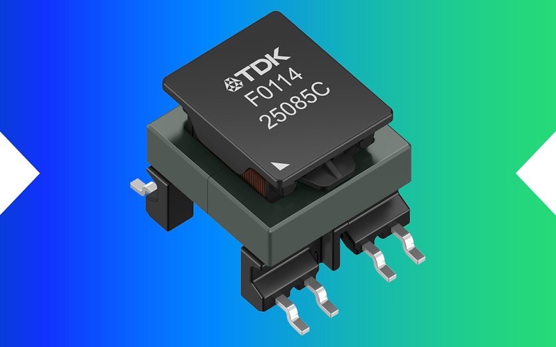
TDK has introduced the E13 EM series, ordering code B8280*F*, for IGBT and FET gate-drive transformer use in automotive 500 V battery systems. The part family is aimed at traction inverters, isolated DC-DC converters, auxiliary power systems, and other xEV power blocks where isolation has to fit into a smaller board area.
The release is useful because gate-driver power is easy to underestimate in an electrified vehicle design. The transformer is not just a small magnetic part near the driver IC. It helps define isolation margin, pulse behavior, thermal reliability, assembly process, and the amount of PCB space left around the power stage. When the inverter or auxiliary converter moves toward a tighter mechanical envelope, that small part can become a real design constraint.
What TDK announced
The E13 EM series uses a compact SMD design based on a MnZn ferrite core. TDK lists an 18.6 x 14.6 mm footprint and a maximum height of 12 mm. The family supports typical operating frequencies from 100 kHz to 400 kHz and includes versions for flyback and push-pull topologies.
The manufacturer also highlights inductance values from about 1.8 uH to 240 uH and saturation current up to 9 A, depending on the selected ordering code. For isolation, TDK states creepage distances up to 6.3 mm, clearance distances up to 5.5 mm, basic insulation at 500 V DC working voltage, and reinforced insulation at 300 V RMS under the stated standards. The series is specified for operation from -40 C to +150 C and qualified to AEC-Q200 Rev. E.
Why this matters at component level
In an xEV power stage, the transformer has to do more than pass energy across a barrier. It has to keep the driver supply stable while the switch node, common-mode voltage, and thermal environment are moving aggressively. A compact SMD transformer can help reduce board area and improve assembly repeatability, but it also moves more responsibility into the PCB layout and qualification review.
The most important practical change is that the transformer can be treated as a defined automotive magnetic component rather than a custom wound item selected late in the design. That can shorten sourcing discussions, but only if the chosen turns ratio, topology, insulation class, and mechanical clearance match the power architecture. A flyback gate supply and a push-pull auxiliary supply are not interchangeable selection problems.
Design checks before selecting E13 EM
| Check area | What to confirm | Why it matters |
|---|---|---|
| Topology | Match the ordering code to flyback or push-pull operation. | The transformer ratio and inductance must support the driver-supply architecture, not just the available board space. |
| Isolation | Review creepage, clearance, working voltage, reinforced or basic insulation, and overvoltage category. | xEV designs usually carry strict safety and validation requirements around the high-voltage barrier. |
| Frequency range | Check the controller frequency against the 100 kHz to 400 kHz operating window stated by TDK. | Running outside the intended range can change loss, regulation, and thermal behavior. |
| Saturation margin | Compare the required peak current with the saturation current of the exact part number. | A headline series name is not enough; the flyback and push-pull variants have different electrical limits. |
| Thermal profile | Model the transformer in the real enclosure, not only at room temperature. | The -40 C to +150 C rating is useful, but board copper, nearby switches, and airflow still decide margin. |
| Manufacturing | Confirm reflow profile, footprint, inspection access, and mechanical keep-out. | SMD packaging helps automation, but the part is still a magnetic component with height and spacing constraints. |
Where the series fits in the BOM
The strongest fit is a design that already needs isolated gate-driver power or a compact isolated auxiliary rail near a high-voltage switching stage. Examples include traction inverter gate-drive supplies, isolated rails around SiC or IGBT power stages, auxiliary DC-DC sections, and AC-DC front-end circuits that need a small qualified magnetic component.
Procurement should not compare this part family only by transformer footprint. The real comparison includes safety documentation, qualification status, orderable code, topology support, lead time, approved vendor list status, and how much redesign would be needed if a second source is not available. For automotive programs, the safer review is to lock the exact ordering code early and keep an alternate design path open until validation data is complete.
What buyers should verify
- Exact ordering code, because the E13 EM family includes several flyback and push-pull versions.
- Turns ratio, inductance, saturation current, and frequency range for the intended controller.
- AEC-Q200 Rev. E documentation and any customer-specific automotive qualification requirements.
- Package drawing, land pattern, maximum height, and creepage or clearance rules on the actual PCB.
- Manufacturer lifecycle status, sample availability, and expected production availability for the target vehicle program.
- Whether the design needs a form-fit-function backup or a second validated transformer option.
How it compares with a custom transformer
A custom transformer can be tuned more tightly to a power stage, but it usually brings more sourcing work, more supplier qualification, and more documentation overhead. A catalog SMD transformer family such as E13 EM can make the early BOM cleaner if the electrical limits line up. The tradeoff is less freedom: the design team has to accept the available ratios, inductance range, package, and insulation structure.
That makes the first engineering pass straightforward. Start with the isolation requirement and topology, then filter by ratio, inductance, peak current, temperature, and package. If the part survives that filter, the next check is not the price line. It is whether the PCB layout can preserve the isolation distances and thermal path that made the component attractive in the first place.
Related In-Fortune reading
- Doing solid power conversion for a connected device
- Powering an AI board so it rides through sudden load
Source and procurement note
The manufacturer announcement is here: TDK E13 EM SMD components for xEV gate drivers and isolated DC-DC converters. Before design-in, confirm the latest datasheet, ordering code, insulation rating, reflow guidance, AEC-Q200 status, and application fit with TDK or an authorized channel.