 Free Shipping Over$200

- Products
- Marking
- Alternative

Doing Solid Power Conversion for a Connected Device
A connected device can have the right radio, the right processor and the right sensor chain, then still fail because the five volt rail behaves like a rumor. Power conversion is the quiet contract between the outside world and the board. It decides what the product does with a wall adapter that sags, a cabinet supply that rings, a cable that drops voltage, a modem burst that pulls current, and a processor that resets if its core rail dips for a moment.
This branch is not about stretching a battery for years. That job belongs to runtime and power management. Here the question is narrower: once energy reaches the product, how should it be turned into rails the electronics can trust? The answer may be an external supply, a board-mount converter, a wide-input buck, a compact switcher, a plain linear regulator, or a small low-dropout rail placed beside the load. Each choice carries heat, noise, cost, layout and service behavior with it.
The first supply boundary sets the rest of the board
A board mount converter against an external supply is not a packaging decision. It is a boundary decision. If the adapter is treated as the product's power supply, then the board inherits the adapter's tolerance, cable drop, plug quality, surge behavior and certification story. If the board carries its own conversion stage, then the enclosure inherits heat, magnetics, switching noise, creepage, service risk and the effort of testing a power path under the loads the product will create. The neat answer in a prototype is often a barrel jack and a module. The shipped answer has to ask who owns failure when the supply is swapped, misplugged, loaded by a long cable, or bought from a second source with a wider output tolerance.
That boundary also decides how much debug evidence the board can give. A product fed by a fixed external five volt adapter may expose only a dead rail when something goes wrong. A board that accepts a wider input can measure the input before conversion, log brownout events, derate features, or keep a housekeeping rail alive while a main rail is shut down. None of that makes the board better by itself. It gives the product a chance to behave intentionally when the incoming supply is poor instead of leaving the firmware to interpret resets after the fact.
The hidden cost of an external supply is variation. A bench adapter has short leads and a clean knob. A customer adapter may have a thin cable, a tired connector and a label that tells only part of the truth. Long cable resistance turns load pulses into rail movement. Connector oxidation turns a radio burst into a voltage step. A cabinet supply can sit beside relays, motors and solenoids. If the board has no input filter, no reverse protection, no transient plan and no input voltage margin, then the connector becomes part of the regulator loop without asking permission.
Put the boundary on paper before the regulator is chosen.
A fixed five volt gateway still needs power discipline
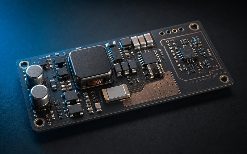
LM2596SX-5.0 in a simple line powered gateway is the familiar version of this story. A non-synchronous buck with an integrated switch can take a higher DC input and produce a five volt rail for a small gateway, relay board or control module. It is attractive because the circuit is understandable: input capacitor, inductor, diode, output capacitor, feedback path and thermal path. It does not ask the designer to build a high-current multiphase regulator or tune a power stage from first principles. It does ask the designer to respect current loops, diode recovery, inductor saturation, capacitor ripple current and the layout around the switch node.
The five volt rail is often treated as a public utility on the board. USB, Ethernet magnetics support circuits, level shifters, sensors, LEDs, relays and downstream regulators all want a share. That makes the rail noisy in both directions. The buck injects ripple and switching edges into the copper. Loads inject their own pulses back into it. A relay coil or modem load does not care that a nearby ADC reference also uses the rail unless the layout, filtering and sequencing keep them from meeting. A five volt buck should be checked under the ugly load pattern, not only the nominal load. If the gateway boots cleanly with the radio disabled, then fails when the network comes up and a relay switches, the regulator may have been judged during the one moment that did not matter.
Ripple has a destination. If the design does not choose that destination with copper and capacitors, it will choose one through the audio circuit, the reset pin, the sensor reference or the cable shield.
Heat is the part the schematic cannot carry. A regulator that looks comfortable at room temperature on an open bench may run in a sealed plastic box, near a processor, behind a sunlit wall, or inside an industrial cabinet with little air movement. The data sheet gives calculations and curves, but the board gives the real copper area, airflow and neighboring heat sources. A simple buck can serve a simple gateway, yet it still deserves a thermal check with the final enclosure and the highest plausible input voltage. When the input rises, the duty cycle changes and switching loss changes. When the load rises, copper and diode losses move. The margin lives in the box, not on the first calculation.
A cheap inductor can turn a quiet prototype into an audible product. Saturation, shielding and temperature rise belong in the same review as regulator price.
Wide input is for dirty places
LMR33630 for a wide input industrial buck points to a harder environment. A field controller or industrial node may see a nominal twenty-four volt rail, a vehicle-like rail, a long cable, a cabinet supply shared with coils, or a plug-in event that brings ringing and dips. Wide input is chosen when the board cannot pretend the source is gentle. It gives the designer room to survive a higher line, lower line, load dump style disturbance within the selected protection plan, and a drop across wiring while the product still needs to stay awake.
The mega issue is not the input range printed on the regulator. It is the complete path from connector to load. A wide-input buck should sit behind protection that makes sense for the installation: fuse or resettable element, reverse polarity plan, transient clamp, input capacitance sized for source impedance, and a layout that keeps surge current away from sensitive ground. Then the converter must be compensated, filtered and laid out so the switch node is small, the hot loop is tight, and the feedback node does not listen to the inductor. The output rail then feeds digital loads that change current in steps. If the load is a processor or wireless module, the response to a fast current edge can matter more than the average output current. If the load is a sensor front end, noise around the switching frequency can leak into the measurement path through ground, reference or cable shield. A regulator selected for input range alone can still make a board that survives power but loses data.
Industrial power work also has a service dimension. A device may be installed by someone who sees only wire color, not the schematic. The connector may be reversed during service. The supply may be shared with a solenoid added later. The cabinet may be rewired by a third party. A wide-input buck gives the board electrical room, but labels, connector keying, input protection and diagnostics decide whether that room is used. In the field, a rail that fails silently can be harder to support than a rail that refuses to start and leaves a logged input fault.
Small bucks save space, then charge rent in layout
MP1584 for a compact high efficiency buck is the other pole: small, common and attractive when the product needs a decent step-down rail in little board area. Compact buck regulators let a sensor hub, display board or wireless node avoid burning heat in a linear regulator. They also put a fast switch, a power inductor and pulsed current close to antennas, ADC traces, reset pins and crystal circuits. A small converter can be quiet enough for many jobs, but only if its current paths are given priority over the tidy placement of the rest of the board. The phrase high efficiency can mislead in a connected device. Efficiency at one amp does not describe light-load behavior, pulse-load response or audible behavior from magnetics. A node that sleeps at low current may spend much of its life in discontinuous mode, pulse skipping or another light-load pattern. That can be fine for a digital rail and poor for a sensitive analog rail. A display or radio burst may pull the converter out of light load and back again. The rail can move in a shape the average current graph hides. Firmware sees the result as a flaky boot, a missed packet, a noisy reading, or a reset that disappears when a bench supply is attached.
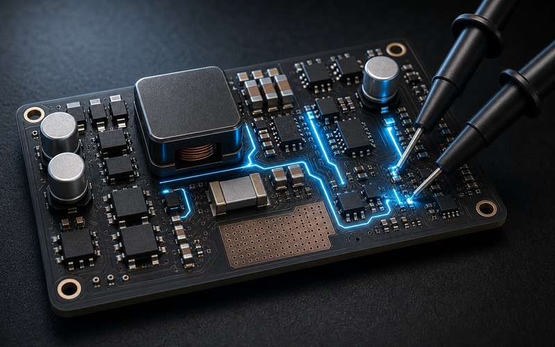
The compact switcher should be placed as a noisy machine on the board map. Keep the input loop tight. Give the inductor current a short path. Keep the switch node small and away from high-impedance nodes. Route feedback as a quiet sense line, not as a decorative trace crossing the power stage. Put the output capacitor where the load step can reach it. Then test the rail with the actual firmware pattern, because a connected product does not draw a resistor load. It scans, connects, transmits, writes flash, lights indicators and sleeps. The converter has to follow those verbs. If that placement cannot be made without crossing a sensitive trace, the board outline, connector location or rail split may be the wrong one, not only the regulator.
Linear regulators are not a moral failure
AMS1117 as a common linear regulator survives because it is cheap, available, understandable and often good enough. It has a clear use: dropping a modest voltage to a local rail when the current and heat are within reason. It can clean up some switching residue, feed a small logic section, or supply a prototype rail with few surprises. The danger is using it as a general answer. A linear regulator turns voltage drop times current into heat. That heat has to leave through the package, copper and enclosure. A board that drops twelve volts to three point three at meaningful current is not making a rail; it is making a heater with logic attached.
The other trap is dropout and stability. A regulator called five volt to three point three is not a magic gap remover. It needs headroom above the output to regulate, and that headroom changes with current, device family and temperature. If the incoming rail falls during a cable drop or load pulse, the LDO can fall out of regulation while the system thinks the rail is still managed. Output capacitor type and ESR also matter for older regulator families. A ceramic capacitor that looks better on a bill of materials can move the loop into a behavior the original part did not expect. Linear parts are easy to place, not exempt from analog work.
RT9013 as a compact low dropout regulator belongs closer to the load, where a small rail needs lower noise, better dropout behavior or a tidier package. A local LDO after a buck can give an RF, sensor, reference or MCU rail some distance from the switcher. It can also isolate load steps so one block does not push noise into another. That does not mean every rail should be cascaded through an LDO. The LDO burns the remaining voltage difference as heat, its power-supply rejection changes with frequency, and its noise performance depends on the part and bypassing. Used with care, it is a local rail shaper. Used as a bandage, it can hide a power tree that should have been split earlier.
The power tree has to match the product's verbs
The right conversion plan starts by writing the product's verbs beside its rails. Boot. Join a network. Transmit. Switch a relay. Sample a sensor. Write flash. Dim a backlight. Sleep. Wake from an interrupt. Recover after a bad adapter is plugged in. Each verb creates a rail shape, not a fixed current. The power tree has to decide which loads share a rail, which loads get a local regulator, which rails start first, which rails can be shut down, and which fault gets logged before the processor loses context. That is why a connected device often mixes methods. A protected input accepts the outside world. A wide or simple buck handles the main energy drop. A compact switcher feeds the current-hungry digital rail. A linear regulator or small LDO feeds the quiet corner. Bulk capacitance handles slower load energy, while local ceramic capacitance handles edge current. Firmware then cooperates by sequencing radio work, delaying flash writes until a rail is stable, and treating brownout as a power event rather than a software mystery. The schematic may show regulators as separate blocks, but the product experiences them as one timed system. A solid power conversion design does not chase the fanciest regulator. It chooses where the heat goes, where the noise goes, where the input abuse stops, and where the load pulses are paid for. When those answers are clear, the radio, processor and sensor chain get to behave like the parts their data sheets promised.






