Free Shipping Over$200

- Products
- Marking
- Alternative

AI Cluster Interconnect Design: Connector, PCB and Retimer Risks
AI Cluster Interconnect Design: Connector, PCB and Retimer Risks
Quick Summary
AI cluster performance is often described as a processor problem. That is too narrow. Once many accelerators, memory pools, switches, storage nodes, power shelves, and management controllers have to behave like one machine, the interconnect becomes a design limit.

The short answer: high-speed interconnect planning should start before layout, connector approval, or cable sourcing. A fast chip cannot make up for a weak channel budget, a poor connector launch, a noisy clock, or a PCB material change that removes signal margin.
Bandwidth is only part of that limit. Signal integrity, connector loss, retimer placement, power noise, clock quality, fiber handling, service access, thermal rise, and production test all affect whether the system works reliably. The expensive chip may get the attention, but a marginal channel can still decide whether the hardware is shippable.
This topic matters for engineers building boards around high-speed processors, FPGAs, network interfaces, camera inputs, edge AI modules, or industrial compute nodes. It also matters for buyers. High-speed connectors, retimers, optical modules, low-loss PCB materials, precision clocks, ESD parts, and test fixtures can become schedule blockers even when the main processor is available.
The practical message is clear: AI interconnect should be planned as a board-level and sourcing problem, not as a cable decision made late in the project.
What Happened
AI systems are pushing more data between devices, boards, racks, and sometimes buildings. That data movement creates a physical design problem. A high-speed link is a channel made from package escape, PCB material, vias, connectors, cable, retimers, clocks, power rails, firmware, and test coverage.
As rack density rises, the supporting infrastructure becomes harder too. More lanes mean more heat, more routing pressure, more connector density, and more ways for a system to fail at the boundary between boards. The interconnect is no longer a passive path between expensive chips.
The useful question is what teams should check when high-speed paths, connector systems, optical modules, and board materials become part of the performance budget.
Component-Level Impact
| Component area | What can go wrong |
|---|---|
| High-speed connectors | Pin count can look right while insertion loss, crosstalk, skew, or thermal rise fails the channel. |
| Retimers and redrivers | They restore margin but add power, heat, firmware, qualification, and sourcing risk. |
| Optical modules and cables | They help with distance and density but add thermal, cleaning, bend radius, and interoperability issues. |
| PCB materials and vias | Stackup, dielectric loss, via design, and impedance tolerance can decide whether the link passes. |
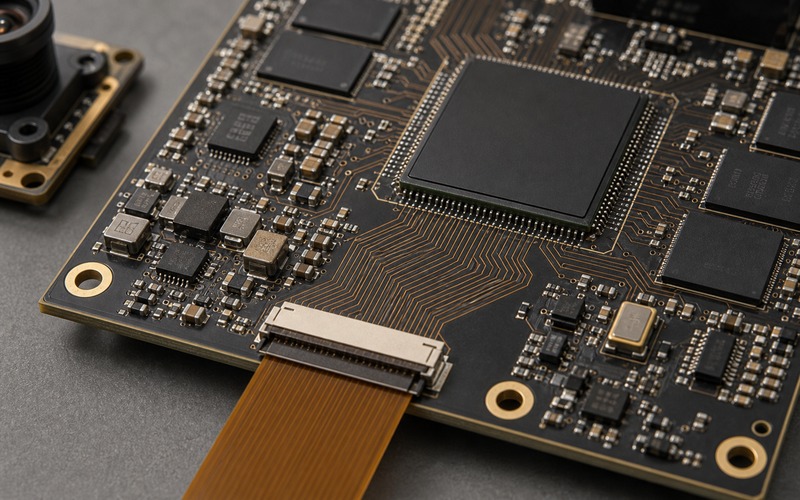
High-speed connectors are the first visible risk. A connector that looks acceptable by pin count can still fail on insertion loss, return loss, crosstalk, skew, mechanical retention, temperature rise, or service life. As lane counts increase, engineers may need mezzanine connectors, board-to-board systems, high-speed backplane connectors, or cable assemblies with tight sourcing control.
Retimers and redrivers are the next group. Longer paths, more connectors, and higher speeds can make a passive channel unrealistic. Retimers add power, heat, firmware, qualification work, and supply risk. They also complicate debugging. If a link is unstable, the cause may be the silicon, connector, cable, board stackup, clock, power noise, or software configuration.
Optical modules and cables can solve distance and density problems, but they bring their own constraints. Availability, thermal load, fiber routing, cleaning, bend radius, interoperability, and module management all need planning.
Clocking parts matter more than they get credit for. High-speed links need clean reference clocks and controlled jitter. A weak oscillator or poor clock distribution plan can turn a good schematic into a marginal channel.
Protection parts must be chosen with signal integrity in mind. ESD diodes, common-mode chokes, isolation devices, and surge protection can damage a channel if they are treated as generic add-ons.
Engineering Design Considerations
The best design habit is to treat the channel as one part number made from many parts. If one piece changes, the channel changes.
Define the full channel before choosing the connector. The channel includes package escape, PCB trace, vias, connector launch, cable, retimer, reference clock, power noise, and receiver margin. Selecting a connector from a catalog before modeling the path invites rework.
Board stackup is an early engineering decision, not a purchasing detail. Low-loss material, dielectric thickness, via design, backdrilling, reference plane continuity, and return current paths shape the margin. If the board vendor changes material or stackup without review, the signal path changes even when the schematic is untouched.
Thermal design needs a link-level view. Retimers, optical cages, dense connectors, and nearby regulators all add heat. A channel that passes in open air can fail inside a compact enclosure with blocked airflow.
Test access should be planned at the start. High-speed channels are painful to debug after assembly. Teams need loopback modes, firmware counters, known-good cables, test fixtures, access points, and clear pass/fail criteria. Without that, a link failure can turn into days of part swapping.
The design also needs controlled variation. If only one cable, one connector plating option, or one PCB material works, the product is fragile. That may be acceptable for a lab demonstrator. It is a bad position for repeatable production.
Sourcing Impact
Interconnect parts are often qualified too late. That is risky because the connector, cable, optical module, retimer, PCB material, and clocking plan form one electrical system. A substitute may fit mechanically and still fail the channel.
Buyers should not approve a second source until engineering has tested it in the full path. For high-speed connectors, small differences in footprint, plating, housing geometry, or launch pattern can matter. For cables, length, shielding, twinax construction, bend radius, and vendor process control matter.
Retimers and optical modules can bring firmware and interoperability issues. A purchasing alternate may require a software change, a different management interface, or a different thermal assumption.
PCB sourcing deserves a stronger review. Low-loss laminates, controlled impedance, via quality, and fabrication tolerance can become hidden constraints. A lower-cost board quote is not useful if it removes the signal margin.
Buyer Checklist
- Ask engineering for the full channel budget before approving connector or cable alternates.
- Confirm required data rate, lane count, insertion loss, return loss, crosstalk, skew, and temperature range.
- Check whether the connector footprint or launch geometry is vendor-specific.
- Ask if retimers, redrivers, or optical modules require firmware support or management access.
- Confirm PCB material, stackup, impedance tolerance, via process, and backdrill requirements.
- Keep known-good cables, modules, and fixtures available for production test.
- Treat ESD and protection parts as signal-path components, not generic line items.
Common Mistakes to Avoid
- Treating a high-speed connector as a mechanical part only.
- Approving a cable alternate without channel-level testing.
- Letting PCB material substitutions happen as a purchasing cleanup step.
- Adding ESD protection without checking capacitance and signal impact.
- Planning test access after the first link failure appears.
Related Reading
- High-speed lanes in an AI device
- Clocking choices that protect system margin
- Antenna and RF front-end integration
What to Watch Next
Watch how much of the link budget moves from copper traces to cable or optics. Also watch whether connector, retimer, and PCB suppliers provide complete reference channels rather than isolated part data. Smaller teams need tested combinations; impressive component specifications alone do not prove a channel.
The strongest sign of maturity will be a qualified ecosystem: connector, cable, retimer, PCB stackup, clocking, thermal data, and test guidance that work together. Until then, interconnect sourcing belongs in the design review from the first layout discussion.