 Free Shipping Over$200

- Products
- Marking
- Alternative

GRM21BR61A476ME15L Murata MLCC: Applications, Selection and Buying Notes
-1,00mm.jpg "GRM21BR61A476ME15L Murata MLCC: Applications, Selection and Buying Notes")
- Part No.:
- GRM21BR61A476ME15L
- Manufacturer:
- Murata Electronics
- Package:
- Description:
- CAP CER 47UF 10V X5R 0805
- Payment:

- Shipping:

Inventory:42,691
Send us your inquiry,we will respond immediately.
Article Details
GRM21BR61A476ME15L Murata MLCC: Applications, Selection and Buying Notes
GRM21BR61A476ME15L Murata MLCC is a GRM-series surface-mount multilayer ceramic capacitor specified as 47 uF, 10V, X5R, 0805 (2012 metric), with +/-20% tolerance. It is used for local decoupling, bulk bypassing and rail stabilization where the board can accept the listed package and voltage rating. View the GRM21BR61A476ME15L product detail page or contact In-Fortune for sourcing support.
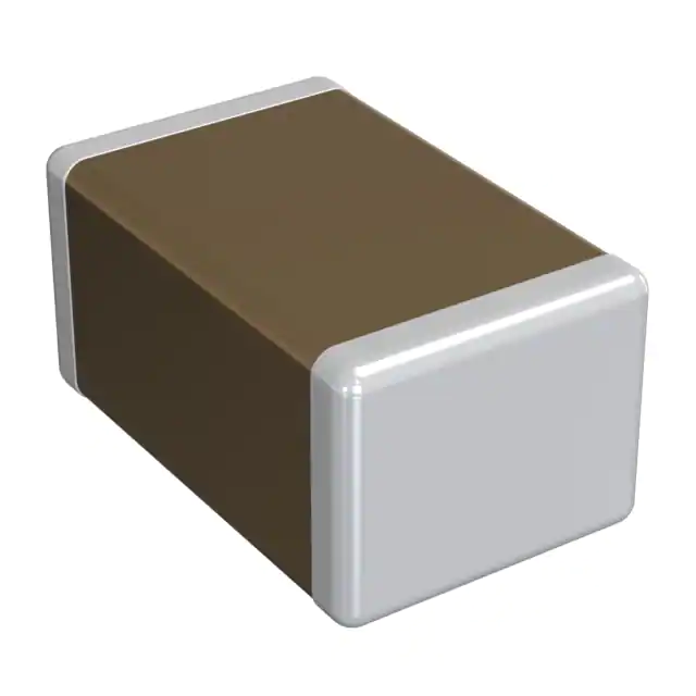
What is GRM21BR61A476ME15L?
GRM21BR61A476ME15L is a Murata Electronics GRM-family ceramic capacitor. In circuit terms, it is a two-terminal, non-polarized MLCC that stores and releases small amounts of charge near an IC, regulator, connector or load step. It is not an active component and it does not have a signal pinout like an IC. The practical pinout check is the land pattern, package orientation, solder fillet and board-level mechanical clearance.
The checked In-Fortune product page describes the part as CAP CER 47UF 10V X5R 0805. Murata product information should be used as the primary engineering source for final approval, especially for DC-bias characteristics, impedance curves, soldering profile, application category and packaging code. The full purchasing model should remain GRM21BR61A476ME15L, because the ending letter can identify packaging and procurement handling.
How GRM21BR61A476ME15L is used
Typical circuit role
Most designs use GRM21BR61A476ME15L as a local energy reservoir on a power rail. A common placement is between the rail and ground near the IC power pin, regulator output, load switch output or module supply input. The capacitor supplies short transient current while the upstream regulator and copper plane respond. In a switching regulator design, it may be part of the output capacitor bank, but the control-loop stability, ripple-current assumptions and effective capacitance under DC bias must be checked against the regulator datasheet.
For decoupling, this part is usually combined with smaller capacitors such as 0.1 uF or 1 uF values placed close to high-speed pins. The larger value handles lower-frequency load movement, while the smaller capacitors help at higher frequency. Layout still matters: short current loops, direct ground return, suitable via count and avoidance of long narrow traces can matter more than simply increasing nominal capacitance.
DC bias, derating and mechanical checks
X5R is suitable for many compact bypass networks, but its capacitance changes with temperature, applied voltage and aging. A 47 uF MLCC will not always deliver its nominal capacitance once a DC voltage is applied. The effective capacitance can drop significantly depending on voltage, package, dielectric and internal design. Engineers should review Murata DC-bias data or measure the rail in the final layout when the capacitor is part of a timing node, regulator compensation plan, hold-up budget or noise target.
The rated voltage must also be compared with the maximum rail, tolerance, overshoot, hot-plug behavior and test conditions. A rail that is nominally below 10V can still exceed the rating during startup or fault events. The board should also be reviewed for flex cracking risk. Larger MLCCs and capacitors near board edges, connectors, screws or depanelization points may need layout relief, soft-termination alternatives or placement changes.
Assembly and pinout notes
For the 0805 (2012 metric) package, the land pattern, solder volume and reflow process should follow the approved footprint. There is no polarity mark to align, but the component still needs correct orientation relative to the pads and pick-and-place file. If an alternative changes package size, terminal material, thickness or reel packaging, the purchasing change can become a PCB and assembly change.
Key specifications for GRM21BR61A476ME15L
| Parameter | GRM21BR61A476ME15L value or review note |
|---|---|
| Manufacturer | Murata Electronics |
| Category | Multilayer ceramic capacitor, SMD MLCC |
| Series | GRM |
| Capacitance | 47 uF |
| Rated voltage | 10V |
| Tolerance | +/-20% |
| Dielectric / temperature coefficient | X5R |
| Operating temperature | -55 to +85 degC |
| Package / case | 0805 (2012 metric) |
| Size / dimension | 0.079" L x 0.049" W (2.00 mm x 1.25 mm) |
| Thickness max | 0.057" max (1.45 mm) |
| Mounting style | Surface mount, MLCC |
| Part status | Active on the checked In-Fortune detail page; final lifecycle to be confirmed with supplier |
| Packaging | Tape and reel; final reel code and quantity to be confirmed with supplier |
| Datasheet / source | Murata product data page and In-Fortune product detail page |
GRM21BR61A476ME15L selection guide
Select GRM21BR61A476ME15L when the design needs 47 uF nominal capacitance, a 10V rated MLCC, X5R temperature characteristic and 0805 (2012 metric) footprint. It is a practical candidate for local bypassing around processors, memory, interface ICs, power-management ICs, sensor modules, communication modules, industrial controls and compact consumer or embedded hardware where a general-purpose GRM MLCC is accepted.
It is a stronger fit when the rail voltage has enough derating margin, the layout already reserves the listed package size, and the design tolerates capacitance shift across DC bias, temperature and aging. It is not the right default when a precision analog time constant, oscillator load, safety-critical hold-up function or high-temperature environment requires a different dielectric, tolerance, certification class or reliability grade. In those cases, review a C0G/NP0 capacitor, a film capacitor, a larger MLCC bank, an automotive-qualified family or a different Murata series.
For procurement, the selection should not stop at capacitance and voltage. Confirm the complete part number, the package code, the thickness, the terminal finish, the reel quantity, the latest Murata data, and whether GRM21BR61A476ME15L is already listed on the AVL. If the design references related parts such as GRM21BR60J476ME15L, GRM31CR61A476ME15L, GRM31CR61E476ME44L, treat each as a separate engineering decision rather than an automatic replacement.
Alternatives and cross references for GRM21BR61A476ME15L
Alternatives are useful for sourcing continuity, but MLCC replacements can fail quietly if only the headline capacitance and voltage are compared. Before approving a GRM21BR61A476ME15L replacement, compare datasheet, dielectric, voltage rating, tolerance, package, thickness, PCB footprint, land pattern, DC-bias curve, ripple and impedance behavior, temperature range, lifecycle status, qualification level and supplier documentation.
| Alternative or related part | Main difference | Replacement risk |
|---|---|---|
| GRM21BR60J476ME15L | 47 uF X5R 0805 at 6.3V | Lower voltage rating can be unsafe on a 10V-approved BOM. |
| GRM31CR61A476ME15L | 47 uF X5R 1206 at 10V | Footprint and mechanical stress behavior differ from 0805. |
| GRM31CR61E476ME44L | 47 uF X5R 1206 at 25V | Larger case and higher voltage class may change DC-bias performance, height and qualification. |
| JMK212BJ476MG series | Taiyo Yuden 47 uF 6.3V 0805 family candidate | Voltage rating and manufacturer approval must be checked before use. |
For a regulator output capacitor, also confirm control-loop stability and minimum effective capacitance over voltage and temperature. For a decoupling network, confirm whether the substitute changes impedance peaks with the rest of the capacitor bank. For mechanically stressed boards, compare termination options and placement risk before releasing a purchase change.
Buying notes and sourcing checks
Before issuing an RFQ for GRM21BR61A476ME15L, confirm the full Murata model, manufacturer name, GRM series, capacitance, rated voltage, tolerance, dielectric, package case, thickness, packaging method, date-code expectation, lot consistency, original factory condition, traceability documents, RoHS/REACH needs, lead time, and accepted substitute range. Do not shorten the request to only 47 uF 10V; that loses the package, tolerance and dielectric details that control the design risk.
Ask the supplier to confirm whether the offered part matches the requested suffix and whether the reel code is acceptable for the SMT process. For GRM21BR61A476ME15L, the purchasing decision should also include application risk: rail voltage, ambient temperature, board flex, regulator stability and customer approval. View the GRM21BR61A476ME15L product detail page. Request sourcing support for GRM21BR61A476ME15L. Contact In-Fortune to confirm GRM21BR61A476ME15L specifications. Send an RFQ with your required quantity and delivery schedule.
GRM21BR61A476ME15L FAQ
Where can I find the GRM21BR61A476ME15L datasheet?
Start with the Murata product data page and the GRM21BR61A476ME15L page on In-Fortune. The final approval sheet, latest product notice and packaging code should be confirmed with supplier before production use.
What is the GRM21BR61A476ME15L pinout?
GRM21BR61A476ME15L is a two-terminal, non-polarized MLCC. The pinout check is the PCB land pattern, package size, soldering geometry and placement clearance, not a numbered IC pin map.
What applications fit Murata GRM21BR61A476ME15L?
Typical applications include power-rail decoupling, local bypassing, regulator output or input capacitor banks, module supply filtering and noise reduction in general-purpose electronic equipment.
Can GRM21BR61A476ME15L replace another capacitor with the same capacitance?
Only after checking voltage rating, dielectric, tolerance, package, thickness, DC bias, temperature range, footprint, lifecycle and qualification requirements. Same capacitance is not enough for MLCC substitution.
Does GRM21BR61A476ME15L have polarity?
No. It is a ceramic MLCC and is normally non-polarized. Assembly still needs the correct package orientation and land pattern for reliable solder joints.
What should engineers check before using GRM21BR61A476ME15L in a regulator circuit?
Check effective capacitance under DC bias, regulator stability requirements, ESR or impedance assumptions, ripple current, startup behavior, voltage overshoot and the total capacitor bank around the regulator.
What should procurement confirm before buying GRM21BR61A476ME15L?
Confirm the full part number, Murata brand, package case, packaging suffix, reel format, date code, lot requirement, original condition, compliance documents, delivery schedule and accepted alternative list.
Related internal links for GRM21BR61A476ME15L
- GRM21BR61A476ME15L product detail page
- Ceramic Capacitors category page
- Murata Electronics manufacturer page
- GRM21BR60J476ME15L product detail page
- GRM31CR61A476ME15L product detail page
- GRM31CR61E476ME44L product detail page
Missing or uncertain data
- Latest Murata approval sheet, product change notice status and customer-specific AVL status: to be confirmed with supplier.
- DC-bias curve, impedance curve and effective capacitance in the final rail condition: to be confirmed against Murata data or measured in the application.
- Exact reel code, standard packing quantity, date-code range and lot requirement for the order: to be confirmed with supplier.
- Any replacement for GRM21BR61A476ME15L must be approved against datasheet, package, land pattern, electrical behavior, lifecycle and certification requirements before use.
GRM21BR61A476ME15L Specifications
- Attributes
- Property Value
- Manufacturer
- Murata Electronics
- Series:
- GRM
- Packaging:
- Tape & Reel (TR)
- Part Status:
- Active
- Capacitance:
- 47 µF
- Tolerance:
- ±20%
- Temperature Coefficient:
- X5R
- Operating Temperature:
- -55°C ~ 85°C
- Features:
- -
- Lead Style:
- -
- Ratings:
- -
- Part Applications:
- General Purpose
- Voltage - Rated:
- 10V
- Failure Rate:
- -
- Mounting Style:
- Surface Mount, MLCC
- Lead Spacing:
- -
- Package / Case:
- 0805 (2012 Metric)
- Thickness (Max):
- 0.057" (1.45mm)
- Size / Dimension:
- 0.079" L x 0.049" W (2.00mm x 1.25mm)
- Height - Seated (Max):
- -
The Posts
-
GRM21BR61A476ME15L Murata MLCC: Applications, Selection and Buying Notes
GRM21BR61A476ME15L Murata MLCC guide for 47uF 10V X5R 0805 decoupling, alternatives, replacement risk and sourcing checks.
-
GRM21BR60J476ME15L Murata MLCC: Applications, Selection and Buying Notes
GRM21BR60J476ME15L Murata MLCC guide covering 47uF 6.3V X5R 0805 use, selection, replacements and supplier checks.
-
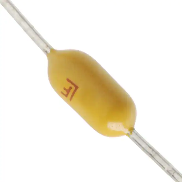
0473003.YRT1L LITTELFUSE Fuse: Applications, Selection Guide, Alternatives and Buying Notes
0473003.YRT1L LITTELFUSE guide for 3 A PICO II 473 slow-blow axial fuse use, 125 V ratings, alternatives and sourcing checks.

-
0451005.MR LITTELFUSE Fuse: Applications, Selection Guide, Alternatives and Buying Notes
0451005.MR LITTELFUSE fuse guide for 5 A NANO2 451 use, obsolete-status review, alternatives, replacement risk and sourcing checks.
-
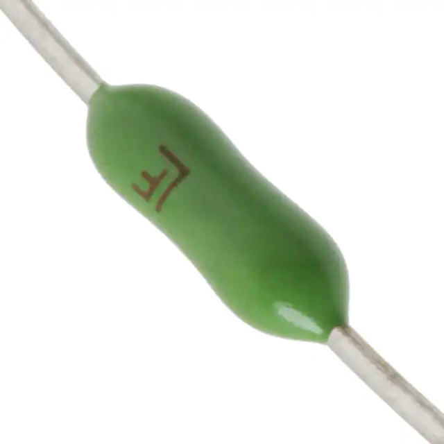
0251.062NRT1L LITTELFUSE Fuse: Applications, Selection Guide, Alternatives and Buying Notes
0251.062NRT1L LITTELFUSE fuse guide for 62 mA PICO II 251 use, 125 V rating, axial PCB fit and sourcing checks.
-
0251001.NRT1L LITTELFUSE Fuse: Applications, Selection Guide, Alternatives and Buying Notes
0251001.NRT1L LITTELFUSE guide for 1 A PICO II 251 axial fuse use, 125 V ratings, PCB fit, alternatives and sourcing checks.
-
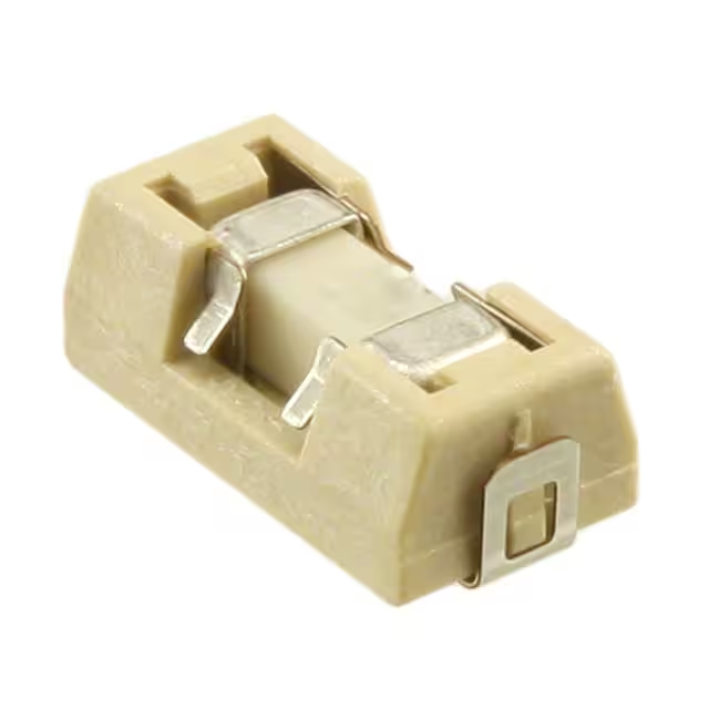
0154001.DR LITTELFUSE Fuse: Applications, Selection Guide, Alternatives and Buying Notes
0154001.DR LITTELFUSE fuse guide for 1 A OMNI-BLOK 154 use, 125 V rating, PCB footprint review, alternatives and sourcing checks.
-
0154.062DR LITTELFUSE Fuse: Applications, Selection Guide, Alternatives and Buying Notes
0154.062DR LITTELFUSE fuse guide covering 62 mA OMNI-BLOK use, 125 V ratings, PCB holder fit, alternatives and sourcing checks.


