 Free Shipping Over$200

- Products
- Marking
- Alternative

Analog Devices Inc./Maxim Integrated MAX5087BATE+T
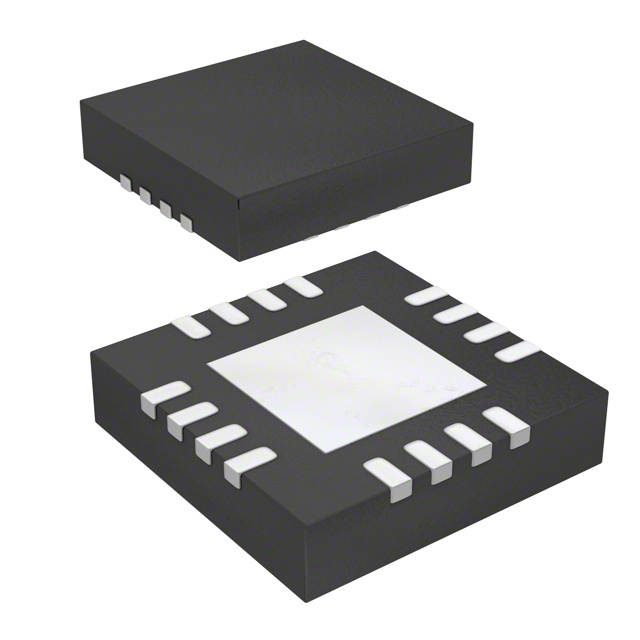
- Part No.:
- MAX5087BATE+T
- Manufacturer:
- Analog Devices Inc./Maxim Integrated
- Package:
- 16-WQFN Exposed Pad
- Datasheet:
-
 MAX5087BATE+T.pdf
- Description:
- IC REG LIN POS ADJ 400MA 16TQFN
- Quantity:
Unit Price:$0.000000
Ext Price:$0.000000
- Payment:

- Shipping:

Inventory:0
Send us your inquiry,we will respond immediately.
In Stock : 0 PCS
| Qty. | Unit Price | Ext Price |
| 0+ | $0.000000 | $0.000000 |
*Products eligible for online ordering ship within 1-2 business days,please contact us for exact shipping times.
Also you can RFQ for MAX5087BATE+T or email to us: Email: [email protected] , we will contact you within 12 hours.
Product Details
MAX5087BATE+T - Maxim MAX5087B 45 V, 400 mA Automotive Linear Regulator, 5 V Preset / 2.5-11 V Adjustable, 70 µA IQ, Programmable Reset, 16-TQFN | MAX5087B
MAX5087BATE+T is the lead-free, tape-and-reel 16-pin TQFN (5 mm x 5 mm) version of Maxim's MAX5087B, a high-voltage linear regulator that runs directly from a 6.5 V to 45 V input and delivers up to 400 mA. It idles at just 70 µA with no load (11 µA in shutdown), ships preset to 5.0 V with a SET pin that re-programs the output anywhere from 2.5 V to 11 V, and integrates a microprocessor reset with capacitor-programmable timeout. Qualified for -40 °C to +125 °C, it is built for always-on automotive modules, supervised MCU rails, 24 V industrial buses and battery-direct standby systems.
Product Introduction
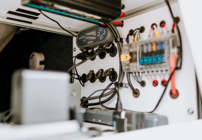
The MAX5087B from Maxim Integrated (now part of Analog Devices) is what a designer reaches for when a module must hang directly on a vehicle battery or a rough industrial supply and still feed clean 5 V logic. Its input stage tolerates 6.5 V to 45 V continuously, so the ordinary 12 V automotive rail - with its cold-crank sags and load-dump style surges toward 40 V - is simply inside the operating range rather than a fault condition. MAX5087BATE+T is the RoHS ("+"), tape-and-reel ("T") option in the thermally enhanced 16-TQFN with exposed pad.
Two numbers define its character. The first is 400 mA of guaranteed output - enough to run an MCU, CAN transceiver and sensor cluster from one device. The second is a no-load quiescent current of only 70 µA: an always-on telematics or body module powered through the MAX5087B barely touches the battery while the vehicle sleeps, and the EN pin can cut that to about 11 µA outright. Output voltage is preset to 5.0 V when SET is grounded (the MAX5087A sibling presets to 3.3 V); strap SET to an external divider from OUTSENSE instead and the same part regulates anywhere from 2.5 V to 11 V against an internal 1.235 V reference.
What separates this from a bare LDO is the built-in supervision. An open-drain RESET̅ output asserts whenever the output falls below roughly 92% of its nominal value and holds the processor in reset for a timeout you program with one capacitor on CT (tRP ≈ CT x 6.175 x 10⁴ seconds per farad) - power supply and voltage supervisor collapse into one package. Thermal shutdown and short-circuit protection guard the pass element; startup to a monitored, valid rail takes under 400 µs, and dropout is a modest 0.8 V (typ, light load). The exposed pad spreads heat from worst-case 45 V-in, 400 mA-out operation into the board.
Expert Technical Insight
What does a 45 V linear front-end buy, and where must the designer be careful?
- Battery-direct without a pre-regulator: the 6.5-45 V window covers 12 V and 24 V systems including their transients, so the MAX5087B replaces a buck-plus-LDO chain in low-current modules - zero switching noise, trivial EMC, two capacitors of external BOM. The trade is linear dissipation: P = (VIN - VOUT) x IOUT, so budget the TQFN's thermal limit (about 2.6 W at +70 °C with good copper) before committing to high continuous current at high input.
- The reset is part of the power design, not an afterthought: RESET̅ releases only after OUT has been above ~92% of nominal for the full CT-programmed delay. Size CT so the MCU's clock and flash are ready before release, and remember the pin is open-drain - it needs its 10 kΩ pull-up and can level-shift to any logic rail.
- Fixed or adjustable changes the feedback wiring: for the preset 5 V, ground SET and tie OUTSENSE straight to OUT at the load (true Kelvin sensing of the actual rail). In adjustable mode the divider from OUTSENSE to GND sets VOUT = 1.235 V x (1 + R1/R2); keep the divider close to the pin and remember the reset threshold tracks whatever output you program.
Key Benefits
A 6.5-45 V operating range rides out cold-crank dips and 40 V-class surges on 12 V/24 V systems - no pre-regulator, no switching noise, automotive -40 to +125 °C.
Just 70 µA no-load quiescent current (11 µA shut down via EN) lets permanently powered modules sleep on the battery for months without draining it.
SET grounded gives a factory-trimmed 5.0 V; one external divider re-programs the same part to any output from 2.5 V to 11 V around a 1.235 V reference.
Open-drain RESET̅ with a capacitor-programmed timeout (CT pin) holds the MCU until the rail is solid - regulator and supervisor in one 5 mm TQFN.
Specifications
| Parameter | Value | Condition / Note |
|---|---|---|
| Device Type | High-Voltage Linear Regulator (LDO) | With µP reset supervisor |
| Manufacturer | Maxim Integrated (Analog Devices) | MAX5087B |
| Input Voltage Range | 6.5 V to 45 V | Battery-direct capable |
| Output Current | 400 mA | Guaranteed |
| Preset Output (MAX5087B) | 5.0 V | SET = GND; MAX5087A = 3.3 V |
| Adjustable Output Range | 2.5 V to 11 V | External divider on SET/OUTSENSE |
| Reference (VSET) | 1.235 V | 1.200-1.260 V limits |
| No-Load Quiescent Current | 70 µA (typ) | SET = GND |
| Shutdown Current | 11 µA (typ) | EN low; 21 µA max |
| Dropout Voltage | 0.8 V (typ) | Light load, VOUT = 5 V class |
| Reset Threshold | ≈92% of VOUT | 89-94% window, open-drain RESET̅ |
| Reset Timeout | tRP ≈ CT x 6.175 x 10⁴ s/F | Capacitor on CT; 2 µA charge |
| Startup Time | ≤400 µs | VOUT 50% to 90% |
| Protections | Thermal shutdown, short-circuit | TJ max +125 °C |
| Operating Temperature | -40 to +125 °C | Automotive range |
| Package | 16-TQFN-EP, 5 mm x 5 mm | ~2.6 W at +70 °C; outline 21-0140 |
| Orderable Part Number | MAX5087BATE+T | Pb-free, tape and reel |
Note: Values are taken from the Maxim MAX5087/MAX5087B datasheet. Confirm every parameter against the latest official documentation before committing a design.
Package Information
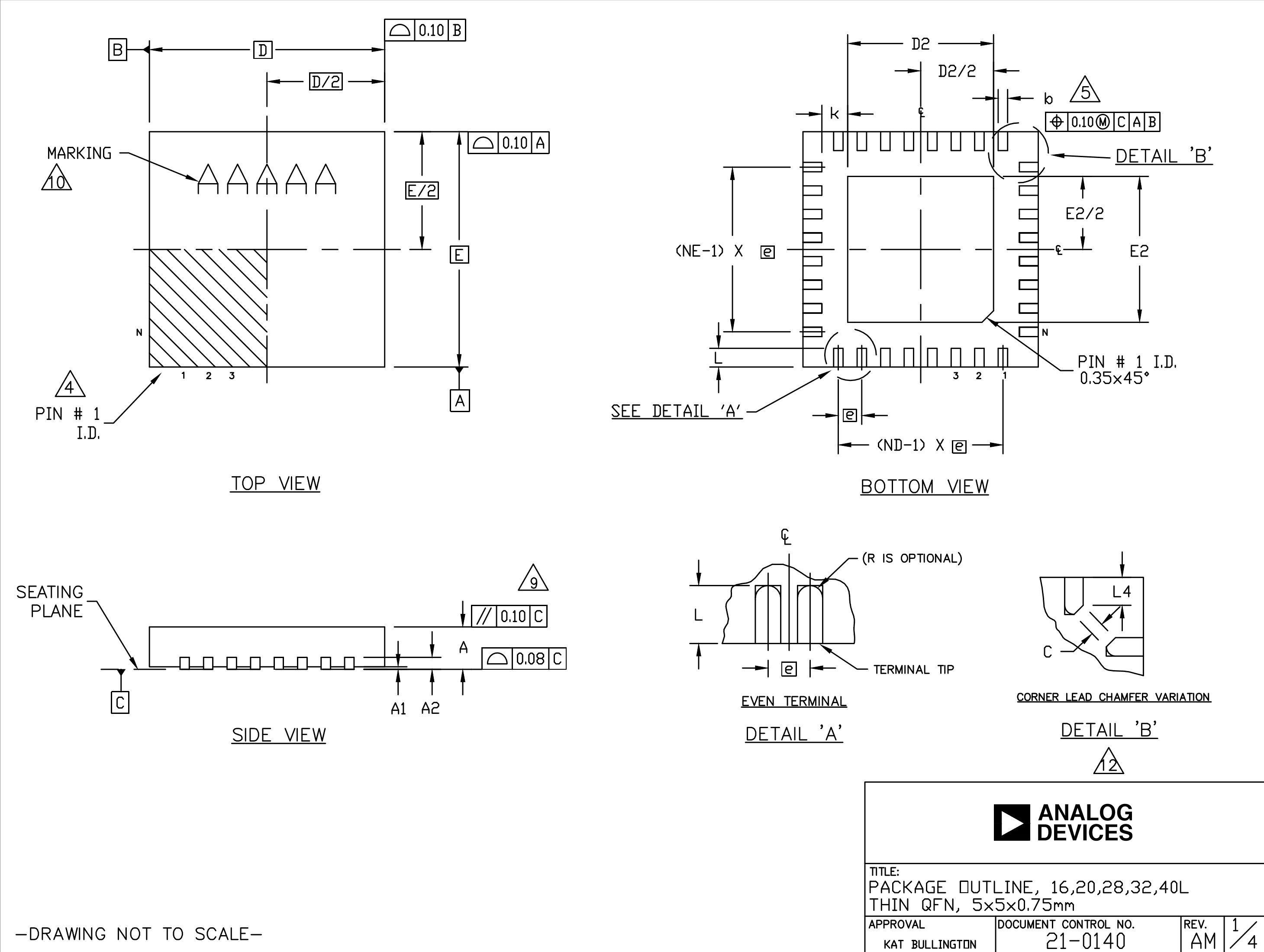
MAX5087BATE+T is supplied in a 16-pin thin QFN with exposed pad, 5 mm x 5 mm x 0.75 mm on a 0.8 mm pitch (Maxim outline 21-0140, land pattern T1655+3). The exposed pad is the thermal path for linear dissipation - solder it to a generous copper pour stitched to the ground plane; electrically it sits at ground but must not serve as the only ground connection (pin 8 does that). With good copper the package handles roughly 2.6 W at +70 °C, which is what permits 400 mA from a high input without a heatsink. Six pins are no-connects, so routing stays loose despite the small body: 47 µF bulk on IN (pins 3/4), 15 µF+ low-ESR on OUT (pins 5/6), divider or strap at SET/OUTSENSE, pull-up on RESET̅, capacitor on CT. The full dimensional drawing is below.
Pin and Signal Definition
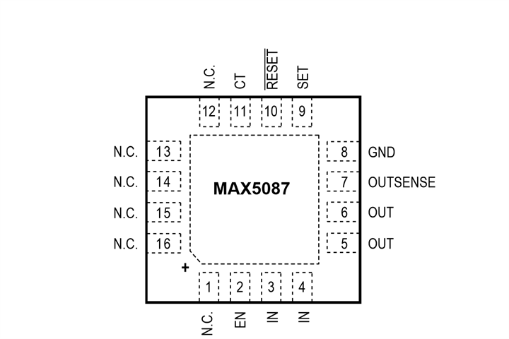
Per the MAX5087/MAX5087B datasheet pin description, the 16-TQFN assigns (N.C. = no internal connection):
- Pins 1, 12-16 - N.C.: Not internally connected; may be left open.
- Pin 2 - EN: Enable input. High turns the regulator on; low enters ~11 µA shutdown. Tie to IN for always-on use.
- Pins 3, 4 - IN: Regulator input, 6.5-45 V; bypass with 47 µF to GND.
- Pins 5, 6 - OUT: Regulator output; stabilize with ≥15 µF low-ESR capacitance.
- Pin 7 - OUTSENSE: Output sense. Tie to OUT for the preset voltage; in adjustable mode it carries the feedback divider.
- Pin 8 - GND: Ground.
- Pin 9 - SET: Output programming. Ground for the preset 5.0 V; connect a divider (OUTSENSE→SET→GND) for 2.5-11 V.
- Pin 10 - RESET̅: Open-drain, active-low reset output; asserts below ~92% of nominal. Needs a ~10 kΩ pull-up.
- Pin 11 - CT: Reset-timeout programming capacitor; tRP ≈ CT x 6.175 x 10⁴ s/F.
- EP: Exposed pad - solder to the ground plane for heat spreading (thermal, not the substitute ground).
Alternative and Related Parts
Closest options are the 3.3 V sibling and Maxim's other wide-input regulators. Confirm output voltage, current, supervision features and package before substituting.
| Part Number | Brand | Type / Key Difference | Package | Note |
|---|---|---|---|---|
| MAX5087AATE+ | Maxim | Same regulator, 3.3 V preset | 16-TQFN | Drop-in for 3.3 V logic |
| MAX15006AASA+ | Maxim | 40 V, 50 mA ultra-low-IQ LDO | 8-SO | Lighter loads, tiny standby |
| MAX15007AASA+ | Maxim | 40 V, 50 mA LDO, fixed/adj | 8-SO | Companion to MAX15006 |
| MAX5023LASA+ | Maxim | 65 V-tolerant micro-IQ LDO + reset | 8-SO | Higher surge headroom |
| MAX5035AASA | Maxim | 76 V, 1 A step-down (switching) | 8-SO | When dissipation forces a buck |
Selection Tips: Keep the MAX5087B where a supervised 5 V rail up to 400 mA must come straight off a 12/24 V battery with minimum noise and parts count; pick the A-grade for 3.3 V systems. Below ~50 mA the MAX15006/15007 or 65 V MAX5023 cut standby current further, and when (VIN-VOUT) x IOUT exceeds the TQFN's thermal budget, step to the switching MAX5035 and post-filter it.
Manufacturer Information
Maxim Integrated, now part of Analog Devices, Inc. (ADI), has supplied automotive power management for decades, and the MAX5087 line is a typical example of its integration philosophy: regulator, precision reference and processor supervisor combined so a battery-connected module needs one IC and a handful of passives.
Under ADI the part carries full AEC-grade documentation - datasheet characterization to +125 °C, thermal data for the 21-0140 TQFN and application guidance on load-dump survival and reset timing - the references that matter when the same board must pass both EMC and cold-crank tests.
Applications


Frequently Asked Questions
Can MAX5087BATE+T connect directly to a 12 V or 24 V battery?
Yes - the input operates from 6.5 V to 45 V continuously, covering 12 V and 24 V systems including cold-crank sags and surge events toward 40 V, with -40 to +125 °C operation. Only the linear power dissipation (VIN-VOUT) x IOUT against the TQFN's ~2.6 W budget limits continuous current at high input.
How do I get an output other than the preset 5 V?
Ground SET for the factory 5.0 V. For any other rail, connect a resistor divider from OUTSENSE through SET to GND; the loop regulates SET to the 1.235 V reference, giving VOUT = 1.235 x (1 + R1/R2), adjustable from 2.5 V to 11 V. The 3.3 V-preset version is the MAX5087A.
How does the reset function work?
Open-drain RESET̅ pulls low whenever the output drops below about 92% of nominal. After the rail recovers, it stays low for a timeout set by the CT capacitor (tRP ≈ CT x 6.175 x 10⁴ s/F), then releases. Add a ~10 kΩ pull-up to the logic supply; tie CT to IN for essentially immediate release.
What external components does it need?
Minimal: 47 µF bulk input capacitance on IN, at least 15 µF low-ESR on OUT, the RESET̅ pull-up, a CT timing capacitor, and - only in adjustable mode - the two-resistor divider. EN ties to IN for always-on operation, and the exposed pad solders to ground copper for heat spreading.
Disclaimer
Information Accuracy: The specifications on this page are based on the official Maxim MAX5087/MAX5087B datasheet. We work to keep the information accurate and complete, but parameters can change with product revisions, so design engineers should verify all values against the latest official documentation before final design.
Product Authenticity Guarantee: All parts we supply are genuine factory originals with full material traceability.
Technical Support: Pre-sales and post-sales technical consultation is available free of charge.
Application Notice: This page is for reference only. Suitability for a specific application should be confirmed by the design engineer against the actual system requirements.
MAX5087BATE+T Specifications
- Specifications
- Attributes
- Property Value
- Manufacturer
- Analog Devices Inc./Maxim Integrated
- Series:
- -
- Package/Case:
- 16-WQFN Exposed Pad
- Packaging:
- Tape & Reel (TR)
- Part Status:
- Active
- Output Configuration:
- Positive
- Output Type:
- Adjustable (Fixed)
- Voltage - Input (Max):
- 45V
- Voltage - Output (Min/Fixed):
- 2.5V (5V)
- Voltage - Output (Max):
- 11V
- Qualification:
- -
- Voltage Dropout (Max):
- 2.2V @ 400mA
- Current - Output:
- 400mA
- Number of Regulators:
- 1
- Current - Quiescent (Iq):
- 150 µA
- Current - Supply (Max):
- -
- Grade:
- -
- PSRR:
- 70dB (100Hz)
- Mounting Style:
- Surface Mount
- Operating Temperature:
- -40°C ~ 125°C
- Control Features:
- Enable, Reset
- Protection Features:
- Over Current, Over Temperature, Short Circuit
- Supplier Device Package:
- 16-TQFN (5x5)
MAX5087BATE+T Relevant information
- MAX5087BATE+T Tags
- Popular Search
The following parts are popular search parts in Voltage Regulators - Linear, Low Drop Out (LDO) Regulators.
The Posts
-
STM32F407VET6 STMicroelectronics MCU Selection Guide
STM32F407VET6 guide covering Cortex-M4 use, 512KB Flash, LQFP100 pinout checks, alternatives and sourcing notes.
-
STM32F103C8T6 STMicroelectronics MCU Selection Guide
STM32F103C8T6 guide covering Cortex-M3 use, 64KB Flash, LQFP48 pinout checks, alternatives and sourcing notes.
-
STM32F405RGT6 STMicroelectronics MCU Selection Guide
STM32F405RGT6 guide covering Cortex-M4 use, 1MB Flash, LQFP64 pinout checks, alternatives and sourcing notes for engineers.
-1,80mm.jpg)
-
GRM31CR61H106KA12L Murata MLCC: Applications, Selection and Buying Notes
GRM31CR61H106KA12L Murata MLCC guide for 10uF 50V X5R 1206 use, obsolete-status review, alternatives and sourcing checks.
-
GRM31CR61E476ME44L Murata MLCC: Applications, Selection and Buying Notes
GRM31CR61E476ME44L Murata MLCC guide for 47uF 25V X5R 1206 decoupling, alternatives and sourcing confirmation.
-2,70mm.jpg)
-
GRM32ER71H106KA12L Murata MLCC: Applications, Selection and Buying Notes
GRM32ER71H106KA12L Murata MLCC guide covering applications, selection, alternatives and sourcing checks for 10 uF, 50V, X7R, +/-10%, 1210 MLCC.
-0,55mm.jpg)
-
GRT155C81E105KE13D Murata MLCC: Applications, Selection and Buying Notes
GRT155C81E105KE13D Murata MLCC guide covering applications, selection, alternatives and sourcing checks for 1 uF, 25V, X6S, +/-10%, 0402 automotive MLCC.
-
GRM155C81E105KE11D Murata MLCC: Applications, Selection and Buying Notes
GRM155C81E105KE11D Murata MLCC guide covering applications, selection, alternatives and sourcing checks for 1 uF, 25V, X6S, +/-10%, 0402 MLCC.
Related Products
-
TPS799185DDCT
Texas Instruments
-
RP115L331D-E2
Nisshinbo Micro Devices Inc.
-
AP2210K-3.3TRE1
Diodes Incorporated
-
LD39050PU25R
STMicroelectronics

-
NCV8163ASN280T1G
onsemi
-
TPS72009YZUR
Texas Instruments
-
RP115L181D-E2
Nisshinbo Micro Devices Inc.
-
TPS79930DDCT
Texas Instruments
-
TPS79918DDCT
Texas Instruments
-
TLV71211DBVT
Texas Instruments
-
TPS79915DDCT
Texas Instruments
-
TPS79925DDCT
Texas Instruments


