A Wide Voltage Input for an Edge Box
A wide voltage input lets one edge box work from factory 12 V adapters, 24 V control panels, vehicle rails, battery packs or a long field cable. That flexibility is useful only when the input path is designed as a product boundary. The first connector, protection stage and buck converter decide whether the box survives the supply that a customer can plug in.
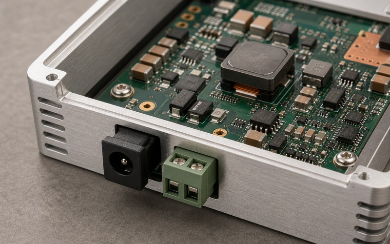
The phrase wide input can hide several separate jobs. The circuit has to accept a stated normal range, reject reverse connection, clamp surge, limit fault current, ride through short dips, start cleanly at low voltage and keep heat inside a closed enclosure. Each job touches a different part, and a part change in one place can shift stress into another part.
For that reason, each candidate part should be checked against the real electrical, thermal, mechanical and sourcing conditions it will face before the board moves into production. The input connector, TVS, fuse, eFuse, MOSFET, sense resistor, buck regulator, inductor, capacitors and copper area form one power-entry system, not a list of separate order lines.
Contents
- Define the Input Range Before Choosing Parts
- Put the Connector at the Product Boundary
- Choose Protection as a Chain
- Size the Buck Converter for the Corner Case
- Plan for Dips, Inrush and Restart
- Control Heat Inside the Enclosure
- Keep Noise Away From Interfaces
- Approve Substitutions by Function
- Wide Input Release Checklist
Define the Input Range Before Choosing Parts
Start by naming the range that the product must support. A box marked 9 to 36 V has a different input stress from a board powered only by a short 12 V adapter. A nominal 24 V industrial rail can see cable drop, charger rise, transient spikes and ground offsets. A vehicle rail can see jump start, load dump, crank dip and noise from motors or relays.
The normal range, absolute range and survival range should be separate. The normal range is where the box must run the workload. The absolute range is where it should remain safe for a defined time. The survival range is where protection parts must prevent damage even if the processor is allowed to shut down. Mixing those three ranges causes undersized connectors, weak TVS parts and hot regulators.
Input current rises as input voltage falls. A converter that provides the same load at 9 V draws more input current than at 24 V, and cable drop also grows. Check connector pins, fuse rating, MOSFET loss, inductor current and copper temperature at the low input corner, with the AI workload, network traffic and storage activity running together.
The range should also name the source impedance. A stiff bench supply, a wall adapter and a ten meter cable do not behave the same way. The cable and source can shape inrush, ringing and dip length. Without that context, a lab result can approve a circuit that fails in the field harness.
Put the Connector at the Product Boundary
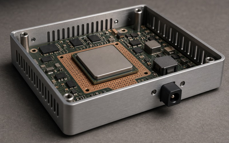
The input connector is the first mechanical and electrical limit. Barrel jack, pluggable terminal, sealed circular connector and wire harness each bring different current rating, retention, polarity control and service behavior. The choice should match who installs the box and how often the cable is touched.
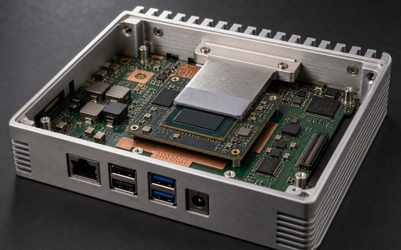
The connector must face the outside of the enclosure. A board-edge connector aimed toward the center of the PCBA forces a cable bend, blocks service access and can stress solder joints. The mating plug, screw clamp, boot, latch and finger access need real keepout space. Check the connector with the enclosure wall and cable in place, rather than relying on a footprint on the PCB.
Polarity marking and keying need care. A two-pin terminal can be wired backward; a barrel jack can use different center polarity; a harness can be assembled with a swapped wire. The circuit should tolerate the error that the installation can create, or the connector system should make that error hard to create.
For outdoor or industrial boxes, the connector also carries sealing and strain concerns. A panel seal can change insertion depth. A cable gland can pull on the board. A field cable can bring ESD and surge energy straight to the input node. Keep protection parts close to the entry point and give the fault current a controlled return path.
Choose Protection as a Chain
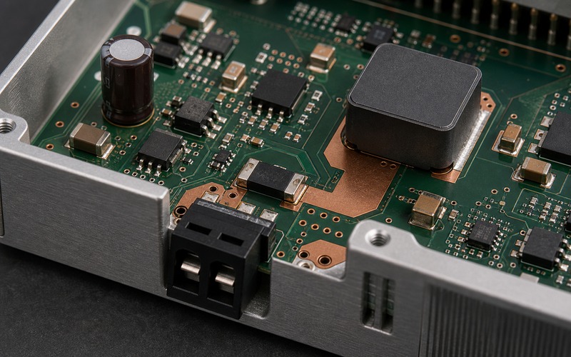
Input protection is a chain. A fuse or resettable protector limits energy. A TVS clamps a fast spike. A reverse-protection MOSFET or diode stops wrong polarity. An eFuse can add current limit, soft start and fault reporting. None of those parts works alone; each part changes what the next part must absorb.
The TVS part must be selected against the normal input ceiling, surge pulse and downstream tolerance. If its standoff voltage is too low, it heats during normal high input. If its clamp voltage is too high, the buck regulator and capacitors see too much stress. The layout also matters: long traces from connector to TVS add inductance and reduce clamp effect.
Reverse protection has a heat cost. A diode is easy to place but loses voltage and power under load. A MOSFET path lowers loss, yet it needs gate control, body-diode behavior review and safe turnoff during transients. If the product draws high current at low input, that loss can become the main source of heat near the connector.
Current limiting should match the fault case. A hard short at the output of the input stage, a stuck load, a hot-plug event and a wrong adapter can all look different. If an eFuse retries too fast in a closed enclosure, it can heat itself and nearby parts. If it latches off, the service plan must say how the user resets the unit.
Ground routing is part of protection. Surge current should not pass under the processor, sensor front end or network PHY before it reaches the return plane. Put the protection path near the input and keep high-energy loops short. If chassis ground is used, define where it joins circuit ground and how that choice affects ESD and conducted noise.
Size the Buck Converter for the Corner Case
The buck converter sees the full input range and the real load profile. A regulator that looks safe at 24 V can run hot at high input because switching loss rises, or it can run hot at low input because current rises. The inductor, MOSFETs, diode if used, sense path and capacitors all need checks across the range.
Start with output power and efficiency, then convert it back to input current at the low input corner. Check peak switch current, inductor saturation, current limit, minimum on-time at high input, dropout at low input and switching frequency choice. A regulator data sheet condition may use an airflow and board area that the edge box does not provide.
The inductor is often the visible part, but its current number is only one part of the review. Saturation current, RMS current, DC resistance, core loss, size, shield behavior and temperature rise all matter. A smaller inductor can fit the board while raising ripple, heat or EMI. A second source with the same inductance can change loss and acoustic behavior.
Input capacitors handle ripple and hot plug stress. Ceramic capacitors lose capacitance under DC bias, while electrolytic or polymer parts add ESR and life limits. Use enough local capacitance to keep the converter stable, but review inrush so the protection stage does not trip during normal connection.
The layout should make the power path visible. Keep the high di/dt loop small, give the inductor and switch node spacing from signal lines, use copper for heat spreading and avoid routing sensitive interfaces through the input power area. A compact edge box can force dense placement, but dense placement still needs a clean current loop.
Plan for Dips, Inrush and Restart
An edge box can see input dips when a long cable carries a load step, when a vehicle starts, or when another device on the rail switches. The design should state whether the box must keep running, shut down cleanly or restart after the dip. Those are different requirements.
Hold-up time depends on load current, input range, capacitor value and the voltage where the converter drops out. A large capacitor can help with short dips, but it raises inrush and can stress the connector, fuse or eFuse. A control signal from the input stage can warn the processor before the rail collapses, giving software time to close files or stop a camera stream.
Inrush needs a defined limit. Hot plugging a charged cable into a discharged input capacitor can create a sharp current pulse. An eFuse or soft-start circuit can reduce the pulse, but it must start at cold and hot temperatures, across source types and with the downstream load attached. If the startup ramp is too slow, the processor or accelerator can sit in an undefined state.
Restart behavior should be tested warm. A converter that starts from cold may fail when the enclosure and inductor are already hot. A brownout can leave a processor, camera, storage device or AI module in different states. The input design should help the whole system reset into a known state, rather than bringing back one rail while other devices remain confused.
Control Heat Inside the Enclosure
The input stage often sits near the enclosure wall, where cable access is good and airflow is weak. Fuse, MOSFET, eFuse, diode, inductor and regulator losses can collect in a small board area. In a sealed box, that heat moves into the enclosure and raises the temperature of nearby processors, radios and storage parts.
Measure the power stage during the load that the product will run. Use low input, high input, full compute load, network activity and the highest ambient case that matters for the installation. Track the connector shell, protection parts, inductor surface, regulator package, nearby capacitors and enclosure wall. A single temperature reading on the processor misses the power-entry limit.
Capacitor life is a thermal issue. Electrolytic and polymer capacitors near an inductor or hot MOSFET age faster. A part that passes electrical review can still be a weak point if placed in a hot pocket. Move heat sources apart where the board allows it, and use copper spreading or thermal vias to prevent a narrow hot strip.
Derating should be visible in the record. Voltage rating, current rating, ripple current, power loss, surge pulse and temperature range should be stated for the selected parts and the allowed substitutes. If the record only lists nominal values, later purchasing changes can erase the margin without warning.
Keep Noise Away From Interfaces
A wide input converter is a noisy neighbor. Switch node edges, input ripple and surge return current can disturb cameras, sensors, Ethernet, USB, audio or radio modules. The input power area should be placed and routed so high-current loops stay away from high-speed lanes and low-level sensor paths.
Filter choice depends on the noise path. A ferrite bead, common-mode choke, LC filter or shield connection can help, but each part can also create resonance or heat. Check conducted noise at the input connector and functional noise at the affected interface. A camera glitch, network drop or sensor offset can be the symptom of a power input issue.
Shield and chassis decisions belong in the same review. A metal box can provide a useful ESD path, yet a careless bond can inject surge current into the signal ground. Define the bond point, any RC or spark gap path and the creepage around high-energy nodes. Keep the design consistent across prototypes and production boards.
EMI fixes should not wait until certification. Leave footprints for damping parts, common-mode parts or alternate capacitors where the risk is high. A small option area near the input is cheaper than a board spin after the enclosure and connector set are locked.
Approve Substitutions by Function
Wide input parts are often substituted during supply pressure because many devices seem interchangeable by voltage and package. That is risky. A TVS with a different clamp curve, a regulator with different minimum on-time, a MOSFET with different gate charge or an inductor with different core loss can change heat, surge tolerance or startup behavior.
Group substitutes by function and test. Connector alternatives need mating, current, shell, panel and cable checks. Protection alternatives need reverse, surge, short and hot-plug checks. Buck alternatives need input range, load step, heat, EMI and startup checks. Capacitor alternatives need capacitance under bias, ripple current, life and inrush checks.
The purchasing note should include package suffix, temperature grade, lifecycle status, source region and approved manufacturers. If the box is expected to ship for years, a single-source eFuse or custom connector can create a program risk even when the circuit passes the lab test.
Keep the approval tied to the product condition. A substitute that works at 12 V on an open bench may not pass 36 V in a closed housing. The allowed list should name the input range, load, ambient, enclosure state and test results used for release.
Wide Input Release Checklist
Before release, review the input range, connector direction, fuse or eFuse, reverse protection, surge clamp, buck regulator, inductor, capacitors, copper path, heat rise, hold-up, startup and noise behavior as one input power system.
The design is ready for release work when it runs the named workload across the required input range, survives the stated faults, starts after hot plug and brownout, keeps connector and power parts inside temperature limits, avoids interface noise and lists approved substitutions with the tests that make them valid.