The Design Limits of a Fanless Edge AI Box
A fanless edge AI box is often chosen for silence, dust resistance and less service work. Those advantages appear only when the thermal path, enclosure, power tree, connector layout and workload are designed as one product. Removing a fan does not remove heat. It changes where the heat must travel, how fast it can leave the board and which part becomes the limit when the box is sealed.
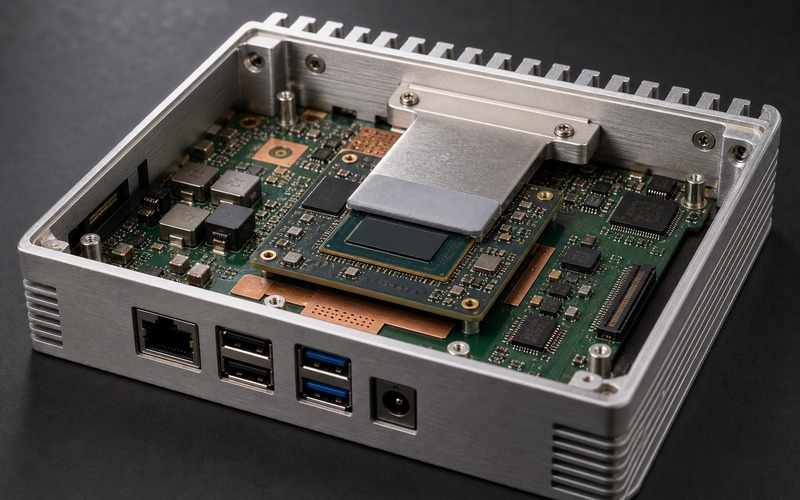
The first prototype can be misleading. A bare board on a bench may run a model for a few minutes, while a closed aluminum box in a cabinet may reach a different temperature after an hour. Cable bend, connector access, dust seals, mounting orientation and ambient range all change the result. A fanless enclosure is a heat sink, a mounting frame and a service boundary at the same time.
For that reason, each candidate part should be checked against the real electrical, thermal, mechanical and sourcing conditions it will face before the board moves into production. The processor choice matters, but the release decision also depends on copper area, thermal pads, regulator loss, connector placement, enclosure finish, workload duty cycle and the tests used to approve substitutions.
Contents
- Start With the Heat Path
- Treat the Enclosure as an Active Part
- Keep Power Conversion Inside the Thermal Budget
- Place Connectors for Real Installation
- Size Workload, Ambient Range and Duty Cycle Together
- Define Manufacturing and Service Limits
- Control Substitution Risk
- Fanless Edge Box Release Checklist
Start With the Heat Path
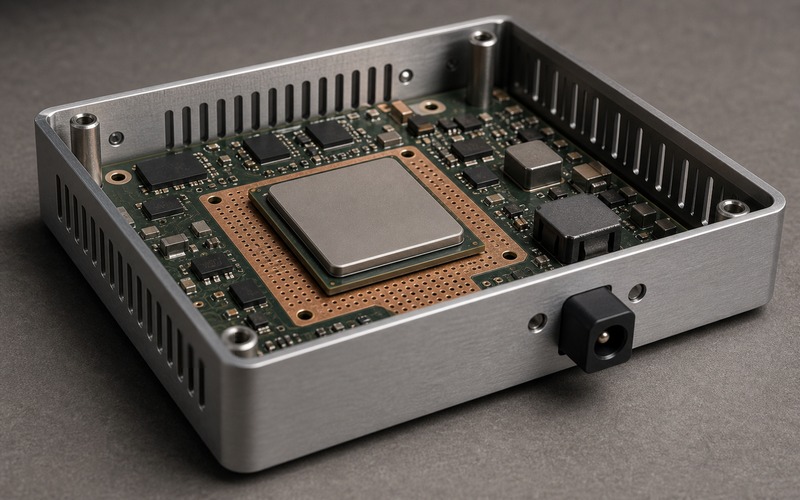
A fanless design starts at the heat source and follows the path to the outside air. The path may run from the processor package into copper planes, through thermal vias, into a pad, through a machined bridge and out through an aluminum wall. If any section is weak, a larger processor or a thicker enclosure will not fix the product by itself.
Map each heat source separately. The AI processor or accelerator may be the largest source during inference, but power regulators, memory, storage and network PHY parts can create local hot spots. A sensor input board or radio module can also sit in a warm pocket near the lid. Heat from each source needs a path, not a drawing note that says the case is metal.
Check contact area and pressure. A thermal pad that barely touches the lid during a hand-built sample can lose contact when tolerance stack, screw torque or PCB bow changes. A tall connector can stop the lid from closing cleanly. A board edge cutout can remove copper near the part that needs it. A product heat path should be reviewed against the actual stack of PCB, standoffs, pads, screws and enclosure.
The test condition must match the installation. A box flat on a lab table cools differently from a box fixed to a wall, a DIN rail, a vehicle bracket or the back of a display. If the product may be mounted in several positions, each orientation needs a defined limit. Natural convection is slow, so time at load matters as much as peak power.
Treat the Enclosure as an Active Part
In a fanless box, the enclosure is part of the thermal design. Material, wall thickness, fin shape, surface area, coating and mounting method all affect heat removal. A smooth decorative case may look clean but reject less heat than a ribbed extrusion with contact to a metal bracket. A plastic window, gasket or label can interrupt a path that looks fine in the CAD view.
The case also controls airflow around the outside. Fins need space. If the box is installed against a flat panel with no gap, the fin area on that side loses value. If several boxes sit side by side in a cabinet, the hot air from one unit can raise the inlet condition for the next unit. The enclosure should be assessed in the real installation cluster, not as an isolated object.
Surface temperature is part of the limit. Some industrial placements allow a warm metal case; consumer or handheld placements may need a lower touch temperature. That decision can reduce the allowed internal heat load even when the silicon still has margin. Define both component temperature and case touch temperature during the design review.
Mechanical details affect heat transfer. Screw count, boss position, gasket height, anodizing, machining flatness and pad compression change contact. If the lid doubles as a heat spreader, the mounting screws become part of the thermal path. If a field technician opens the lid, the design should guide the pad and bridge back into the correct position during service.
Keep Power Conversion Inside the Thermal Budget
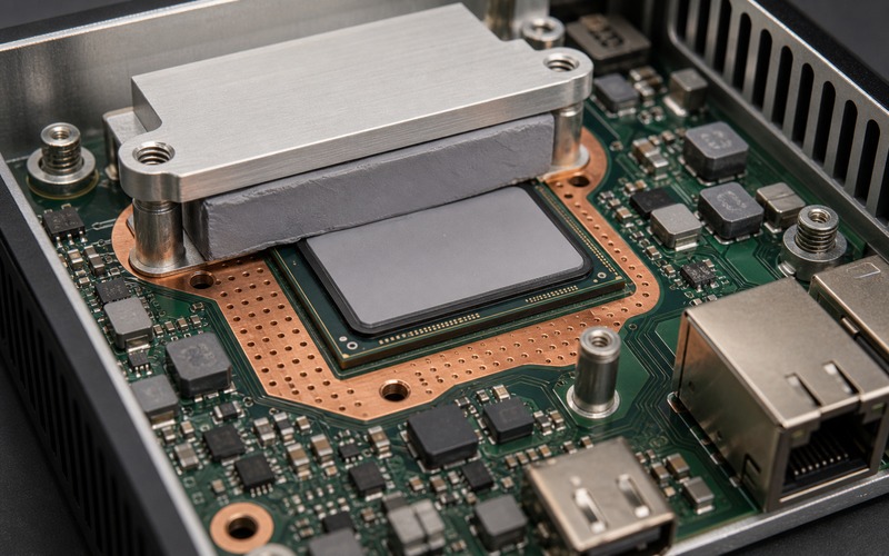
Power conversion can decide the limit before the AI processor does. A wide input range, protection circuit, buck converter, load switch and local low-noise rails all lose power as heat. A box that accepts 9 to 36 V may dissipate more in its front-end path than a bench unit fed from a short 12 V adapter.
Review the input connector, fuse or eFuse, reverse protection, surge path, buck converter, inductor, current sense part, output capacitors and grounding as a chain. The converter should be checked at the low input and high load corner, where current is higher. Inductor saturation, diode or FET heating and copper spreading can become the real operating cap.
Power sequencing also belongs in the design limit. The AI module, memory, network interface and storage device may need a stable order at boot and at brownout. If a hot restart leaves the accelerator locked or the network link down, the hardware has failed the product case even if the voltage rail passes a steady bench test.
Input events are harsher outside the lab. Cable hot plug, long lead inductance, vehicle load changes, outdoor adapters and installation mistakes can stress a compact power path. Protection parts should be selected for the actual input domain, and their heat rise should be measured during repeated events when the box is already warm.
Power margin should be tied to workload. A light model with low frame rate may leave enough room, while a new model, high-resolution stream or extra Ethernet traffic can raise both processor and converter heat. The design release should name the workload, model version, frame rate, ambient range and input voltage used for approval.
Place Connectors for Real Installation
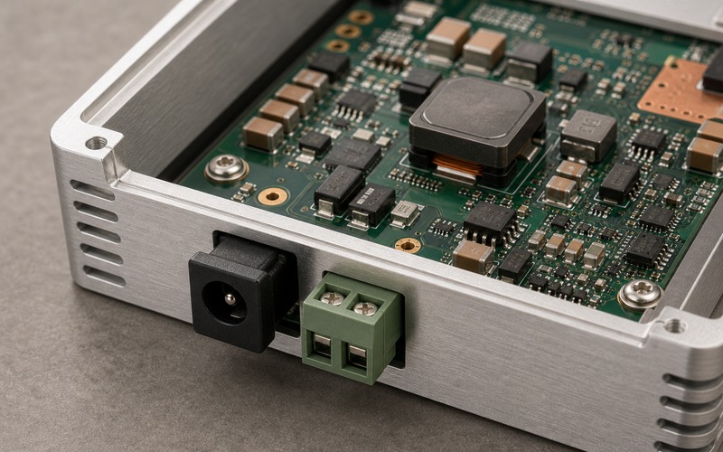
A sealed edge box still needs cables. Ethernet, USB, power, antenna, camera, serial, GPIO and debug connectors all need a direction, a retention method and a keepout. Board-edge connectors should face the enclosure wall where a cable can enter from outside. A connector aimed toward the center of the PCBA creates bend stress, blocked access and assembly confusion.
The connector field should be checked with the mating cable, boot, latch and finger access in place. A power plug can block a USB port. A tall RJ45 shell can interfere with the lid or thermal bridge. A cable with strain relief can need more depth than the bare connector footprint suggests. The mechanical keepout must include the cable that the customer will use.
For wireless versions, the antenna path has its own direction rule. A coax pigtail should not cross a hot heat spreader or sharp lid edge. A board antenna needs clearance from the metal enclosure or a defined plastic window. If the antenna exits through a bulkhead connector, the connector orientation and ground contact need the same care as Ethernet and power.
Service access should be planned early. A debug header, reset button, storage slot or SIM holder that is buried under a heat bridge may help a prototype but slow factory work. Decide which access points remain open in production and which are removed or covered. That choice should match the support plan, not the convenience of the bench build.
Size Workload, Ambient Range and Duty Cycle Together
A fanless edge AI box is specified by a workload, not by a processor data sheet line. Model architecture, input resolution, frame rate, preprocessing, network upload, storage writes and local display output change the heat profile. The same hardware can pass a presence detection workload and fail a multi-stream inspection workload.
Duty cycle is part of the limit. A box that runs inference for two seconds after an event has a different thermal state from a box that runs full rate all day. Burst work still needs peak power margin, but sustained work sets the enclosure temperature. Test both if the product has wake, classify, transmit and idle phases.
Ambient range must be realistic. A device rated for an indoor office does not need the same margin as a unit mounted in a roadside cabinet, a vehicle, a factory ceiling or a rooftop sensor pole. Solar load, closed cabinets, nearby drives and dust can raise the local condition beyond the weather report. The approved range should describe the installation and the air temperature together.
Thermal throttling is a design signal, not a harmless software feature. If the processor reduces speed during normal operation, frame rate, latency and model accuracy can shift. If the regulator enters current limit, the failure may appear as camera loss, storage error or network reset. Log performance and errors during heat soak, then power-cycle the unit while warm.
Keep a margin record. Record processor temperature, regulator temperature, enclosure surface temperature, input voltage, current, model version, camera settings and mounting orientation. That record lets engineering and purchasing decide whether a later part change fits the approved envelope.
Define Manufacturing and Service Limits
A fanless box can fail in production if the assembly process is vague. Thermal pad placement, pad thickness, screw torque, board seating and connector alignment must be repeatable. A pad shifted a few millimeters can create a hot spot. A screw tightened out of sequence can tilt a heat bridge. A connector shell slightly off-center can make the port hard to use.
Inspection should look for mechanical and thermal details as well as boot status. The line should confirm pad presence, bridge seating, lid clearance, connector alignment, cable latch, gasket position, screw torque and label placement. A short powered test should include camera or network activity, rather than a blank idle boot screen.
Service limits need the same clarity. If the box can be opened, the service procedure should name which pad or gasket must be replaced and how the bridge is seated. If the box is sealed, the plan should state how firmware restore, log capture and failure analysis will happen without opening the product.
A fanless design can also make rework harder. Heat bridges, heavy copper and metal walls hold heat during soldering. Tall connectors near the case wall may need special tools. Put that work into the manufacturing review so substitutions and repairs do not damage neighboring parts.
Control Substitution Risk
Substitution in a fanless edge box is a system decision. A pin-compatible regulator can have different efficiency and heat rise. A processor module with the same footprint can draw a different peak current. A thermal pad from a second supplier can change compression and contact. A connector with the same pins can have a different shell height or cable latch.
Separate fixed, controlled and flexible items. Fixed items may include the processor module, thermal bridge, enclosure extrusion and camera module when they define the performance envelope. Controlled items may include regulators, inductors, pads, connectors and storage devices that can change after a defined test. Flexible items should still meet voltage, current, temperature, package and lifecycle checks.
Approved alternatives should name the test they require. A regulator change should trigger load, heat and startup checks. A pad change should trigger compression and heat path checks. A connector change should trigger mating cable, shell, latch and panel fit checks. A processor or AI module change should trigger workload, driver, power and heat testing.
Purchasing data also matters. Lifecycle status, package suffix, reel format, minimum order, supplier region and date code policy can change which option is practical for production. The sourcing note should sit next to the engineering note so the final bill of materials is both buildable and supportable.
Fanless Edge Box Release Checklist
Before a fanless edge AI box is treated as production hardware, review the complete path from heat source to outside air, the enclosure role, power conversion loss, connector direction, workload duty cycle, ambient condition, manufacturing repeatability and allowed substitutions.
The design is ready for release work when it can run the named workload in the closed enclosure, in the required mounting position, across the input voltage and ambient range, without thermal shutdown, unstable links, cable stress or service steps that depend on hand-built judgment. At that point, the processor, enclosure, regulators, thermal materials, connectors and approved alternatives can be managed as one product package.