Free Shipping Over$200

- Products
- Marking
- Alternative

Raspberry Pi 5 with an Add on Accelerator for Edge Vision
Raspberry Pi 5 with an Add on Accelerator for Edge Vision
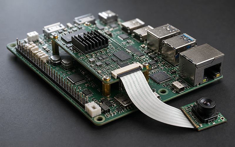
A Raspberry Pi 5 class board becomes more than a development platform when an add-on accelerator is asked to carry an edge vision workload. The board may already boot, expose camera connectors and offer familiar I/O, but the accelerator turns the assembly into a system with its own power, heat, cable and software boundaries.
The practical decision is not whether the accelerator can run a demo model. It is whether the board, adapter, camera path, enclosure and image can run the same workload in a box that survives repeated boot cycles, cable handling, temperature rise and field updates.
That makes this build different from a plain camera board. The extra module changes rail current, connector height, airflow, mechanical clearance, driver support and purchasing risk. Each part should be checked against the real electrical, thermal, mechanical and sourcing conditions it will face before the board moves into production.
Start With the Accelerator Interface
The accelerator interface sets the first boundary. Some add-on accelerators use an M.2 style socket, some attach through PCIe on a mezzanine board, and some arrive as HAT-style modules with a board-to-board or cable path. The selection is less about the label and more about the link width, clocking, reset behavior, power pins, mechanical height and software support that come with that interface.
Check the host board revision, adapter board, flex cable if used, and accelerator module as one stack. A connector that works on an open bench can lose margin when the lid presses on the cable or when a standoff bends the add-on board. The mechanical stack also affects thermal contact, since a tall accelerator may block airflow around the processor, regulators or camera connector.
Keep the accelerator link short and controlled. If the path uses a rigid adapter, review connector seating and board support. If it uses a cable, review bend radius, retention, shield termination and how the cable exits the product. Treat the accelerator as a high-speed assembly with a power budget, not as a plug-in accessory that can be moved late in the design.
Keep the Camera Path Separate From the Compute Stack
Edge vision starts with the camera path. The sensor connector, FPC ribbon, lens holder, bracket and enclosure window decide what the model sees before the accelerator does any work. A loose camera ribbon or a connector hidden under the add-on board can turn a stable prototype into a fragile product.
Place the camera FPC connector where the ribbon can leave the board without folding under the accelerator or crossing a heatsink. The cable should have a clean service direction, enough clearance at the latch and strain relief in the enclosure. The camera module should mount to a bracket that holds optical alignment rather than floating at the end of the ribbon.
The camera interface should also be kept away from noisy power conversion where the layout allows it. A compact board may force tight routing, but power inductors, switching nodes and high-current copper should not crowd the camera connector or ribbon exit. If multiple camera lanes or higher resolutions are planned, reserve routing and mechanical space early instead of adding them after the carrier shape is frozen.
The image pipeline links hardware and software. Sensor choice, lens field, exposure behavior, ISP support, driver version and model input size all interact. Changing the camera module can change cable length, FPC pitch, mount height and calibration work, so approved alternatives need more than a matching connector footprint.
Build the Power Tree Around Peak Vision Load
A host board plus accelerator plus camera has a different load shape from the host board alone. Boot, camera start, model load, network activity and sustained inference can pull current from different rails at different times. A supply that looks steady during desktop use may sag when the accelerator and camera begin work together.
Start at the field input and move inward. Check adapter rating, cable drop, input protection, fuse or eFuse behavior, buck converter current margin, inductor saturation, output capacitance, connector rating and ground return. Measure the host board rail and accelerator rail at the points where the load enters the boards, rather than only at the power adapter.
The add-on board may carry local regulators, but the upstream board still sees the load. A small adapter can hide hot regulators, thin copper or a connector pin limit. If the accelerator is powered through a header or flex path, verify that the path can handle the current and that a reset or brownout does not leave the host and accelerator in different states.
Input protection should match the installation. A bench supply with a short cable hides events that appear when a wall adapter, field harness or exposed connector is used. Reverse polarity, hot plug, ESD, cable pull and accidental short behavior should be reviewed before the accelerator board is treated as a stable extension of the host.
Power testing should use the same camera resolution, model, frame rate and network behavior expected in the product. A static benchmark can miss repeated capture bursts, storage writes or network upload bursts that overlap with inference. Log voltage and temperature through a long run, then power-cycle the unit while warm to catch startup margin issues.
Give the Accelerator a Real Heat Path
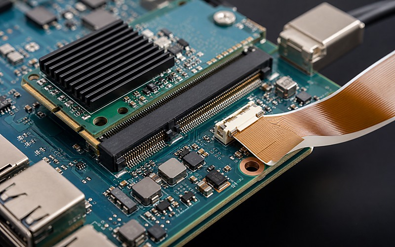
The host processor, accelerator, power regulators and camera electronics all add heat to a small space. A finned heatsink on the add-on card may look complete while the board below warms the enclosure and the camera ribbon blocks airflow. Cooling needs a path from silicon to a surface that can reject heat, beyond a black heatsink in the photo.
Review the stack height, thermal pad compression, nearby connector plastic, airflow channel and enclosure material. If the box is fanless, the heat path may need a pad or bridge from the accelerator to a metal lid. If a fan is allowed, the air path should not be blocked by the camera ribbon, tall headers or cable loops.
Thermal material also has a sourcing angle. A pad that meets the height stack in one prototype may compress differently after a supplier change. Record pad thickness, softness, contact area and mounting pressure with the same care used for electrical parts. A later material swap can change module tilt, connector stress and heat transfer at the same time.
Thermal testing should run the full vision task long enough for the enclosure to warm. Watch for throttling, image errors, USB or Ethernet dropout and regulator heating. If the camera is close to a hot module, also check whether heat drift affects focus, exposure stability or sensor noise. The goal is a stable operating envelope, not a single peak number taken with the lid open.
Treat Connectors and Height as Product Constraints
A single-board computer gives access to many connectors, but a product should expose only the ones it can protect and service. USB, Ethernet, power, camera FPC, GPIO, fan, display and debug access each need a direction, retention method and keepout. Board-edge connectors should face the enclosure wall where a cable can enter from outside, not toward the center of the PCBA.
The add-on accelerator can create height conflicts with a heatsink, camera cable, lid, standoff or nearby connector. Check the stack in the actual enclosure model. A ribbon that bends over a heatsink may work once, then crack or lift after service. A tall module can also shadow nearby components, making inspection and rework harder.
Mounting is part of the electrical design. Unsupported adapter boards can vibrate, creep out of connectors or stress solder joints. Add standoffs or brackets where the assembly needs them, and leave enough access for factory insertion, visual inspection and later service. The accepted mechanical stack should be recorded with the approved bill of materials.
Match Software Support to the Hardware Stack
An add-on accelerator is only useful if the software image recognizes it in the same form that will ship. Kernel version, driver package, runtime library, model format, device permissions, camera stack, boot configuration and update policy all become part of the hardware selection.
Keep the prototype image separate from the production image. Development packages, loose passwords, experimental drivers and hand-edited scripts can make a bench unit convenient, but they make production hard to repeat. The final image should bring up the camera, accelerator, network and storage path in a predictable order and expose enough logging for factory checks.
When an accelerator card, adapter or camera changes, rerun the software path. A replacement module may use the same socket while needing a different driver, firmware blob, thermal policy or model conversion step. A camera with the same connector may need different tuning or exposure settings. Put those checks into the substitution rule rather than leaving them to field troubleshooting.
Restoration also belongs in the plan. The unit should survive a failed update, a corrupted model file or a power loss during configuration. A service header, restore button, known boot media, watchdog and clear reimage method can turn a failed unit into one the factory can bring back without replacing boards.
Define What Can Be Replaced
The accelerator, adapter board, power supply, camera module, FPC cable, storage device, heatsink, fan and enclosure hardware do not have the same substitution risk. Some parts can change after a fit and function check. Others force driver changes, thermal testing or optical validation.
Separate the bill of materials into fixed, controlled and flexible items. A fixed item may be the accelerator family tied to the runtime. A controlled item may be the camera module, where a second source is allowed only after image tuning and bracket checks. A flexible item may be a passive part on a support rail, provided voltage rating, tolerance, package, temperature range and placement still match the approved layout.
Write the approved alternatives around checks. For the accelerator, check interface compatibility, driver support, model runtime, power draw, heat path and module height. For the camera, check connector pitch, cable length, lens mount, image tuning and mechanical bracket. For the power path, check connector rating, regulator margin, inductor current and thermal rise.
For buyers, keep the sourcing note concrete. If the approved accelerator or camera becomes hard to source, the replacement review should name the tests needed before purchase approval. If the adapter board is custom, keep its connector and mounting parts in the same lifecycle review as the active components.
The review should also name what data must be kept with each build: board revision, adapter revision, camera module, cable length, accelerator firmware, model version, operating image and thermal hardware. Without that record, a field issue can look like a component shortage, a software fault or a mechanical problem depending on who sees it first.
Edge Vision Release Checklist
Before a Raspberry Pi 5 class edge vision build is treated as product hardware, review the accelerator interface, camera FPC path, power tree, thermal path, connector exposure, mechanical stack, software image, restore method and approved alternatives as one design.
The build is ready for release work when it can boot repeatably, bring up the camera and accelerator, run the target model through heat soak, return from a failed update, pass factory test and accept substitutions only after electrical, thermal, mechanical, optical and software checks have been completed.
Related information
- 2026.07.08 A Wide Voltage Input for an Edge Box
- 2026.07.08 The Design Limits of a Fanless Edge AI Box