The Thermal and Power Ceiling That Shapes an Edge AI Design
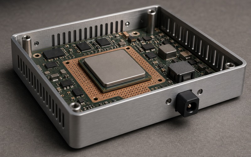
An edge AI design is often decided before the processor is named. The first limit is the box: how much power can enter, how much heat can leave, how loud the product can be, how hot the surface may get and how much room is left after connectors, cables and mounting hardware are fixed.
A faster module can look attractive on a bench and still be wrong for the product. If the enclosure cannot remove the heat, the model will throttle, the rail will sag, the camera will warm, the radio may lose margin and the customer will see a slower device than the bill of materials promised.
The useful review treats the compute module, power input, regulator losses, copper area, heat spreader, enclosure wall, vent path and workload as one design boundary. The boundary is not a spreadsheet total alone. It is a physical path through the product.
The goal is to choose a board and component set that can hold the intended workload in the final enclosure, with enough margin for aging, temperature spread, assembly variation and approved substitutes.
Begin With the Enclosure, Not the Benchmark
The enclosure sets the shape of the thermal problem. A sealed metal box, plastic gateway, handheld camera, rail-mounted controller and outdoor sensor node move heat in different ways. A module that behaves well on an open bench may reach a different power state once the lid is fitted.
Begin with the physical limits: volume, wall material, surface temperature target, mounting face, cable exits, gasket line, vent permission, fan permission, dust exposure and service access. These choices decide whether heat can leave through a spreader, chassis wall, vented air path, mounting bracket or a small internal copper reservoir.
The benchmark result comes later. It is useful only if the test power, ambient condition and cooling path resemble the product. A short neural-network run with an open heatsink cannot approve a fanless box that will sit warm for hours.
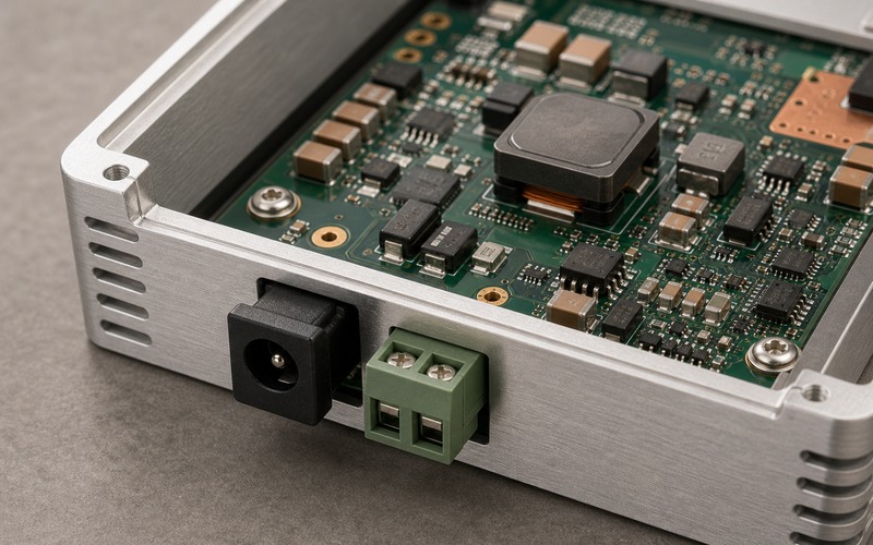
Mechanical placement can force the electrical design. A power jack at one wall, camera cable at another, antenna keepout on top and heat spreader in the center may leave only a narrow area for regulators and memory. The product boundary has already limited the board before schematic work is finished.
Build a Power Budget That Includes Losses
Power budgeting is more than adding processor watts. Input protection, regulators, memory, storage, camera modules, displays, radios, sensors, relays, LEDs and housekeeping rails all draw current. Each conversion step also throws away power as heat.
Use operating states that match the product. Boot, idle listening, image capture, inference burst, continuous recording, radio upload, charging, sleep and fault recovery can each stress a different rail. The board may pass one state and fail another if the regulator, inductor or input connector is undersized.
The budget should show peak and sustained demand separately. Peak demand sizes inrush, current limit and transient response. Sustained demand sizes heat. A compact box can ride through a short peak and still fail under a lower long load because the enclosure continues to warm.
Cable and input conditions belong in the review. A long cable, power-over-Ethernet source, battery pack, wall adapter, automotive rail or field supply can create voltage drop, surge, brownout or thermal stress at the entry point. The front end must survive the source before the processor can use the power.
Regulator efficiency curves must be checked at the expected current, input voltage and temperature. A part that looks efficient at one load point may lose more heat near the product duty cycle. Inductor loss, diode loss, switching frequency and copper spreading can shift the thermal result.
Turn Power Into Heat Before Choosing Compute
Every watt that enters and does not leave as useful work becomes heat in the box. That heat is created across the compute module, regulators, memory, interfaces and protection parts. If the thermal path is weak, increasing compute rating can reduce delivered inference speed because firmware throttles earlier.
The compute choice should be filtered by sustainable power, not peak marketing capability. A module that can draw a higher peak may need a larger heatsink, wider copper, stronger adapter, greater airflow or a metal wall connection. If those items cannot fit, a lower-power design may deliver steadier output.
Workload shape matters. Vision workloads may heat image sensor, memory and accelerator together. Voice workloads may keep audio and wake-word blocks alive for long periods. Gateways may combine wireless upload with inference and storage writes. The heat map changes with the workload, so a single processor number cannot set the design alone.
Thermal throttling should be treated as a product behavior, not a failure note. If the product is allowed to reduce frame rate, duty cycle or model size under heat, that policy must be written into the requirement. If the customer expects full-rate operation, the mechanical and power design must support it.
The early trade is direct: model size, latency, frame rate, input resolution, local storage, radio duty cycle, enclosure size, surface temperature and adapter rating all compete for the same ceiling. A clean selection process makes that trade visible before the board is routed.
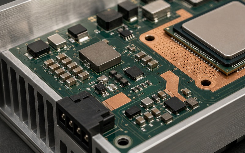
Place Heat Sources So the Board Has an Exit Path
Hot parts should not be scattered without a heat plan. Processor, regulator, memory and radio sections need copper, vias and a route to metal or air. If each heat source warms the same small region, the local board temperature rises and derating disappears.
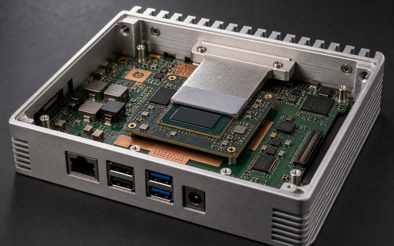
A heat spreader can help only when it has contact pressure, area and a place to send heat. It may bridge the processor to the enclosure wall, but it can also trap heat if the enclosure has no path to air or mounting metal. Standoffs and screw bosses become part of the heat path when they touch metal.
Power parts deserve their own layout review. Inductor, MOSFET, diode, module and current-sense parts need short high-current loops, copper area and clearance from heat-sensitive sensors. A regulator placed beside the compute module can raise the starting temperature of the processor.
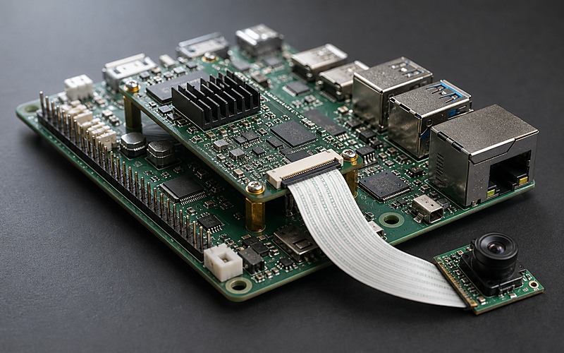
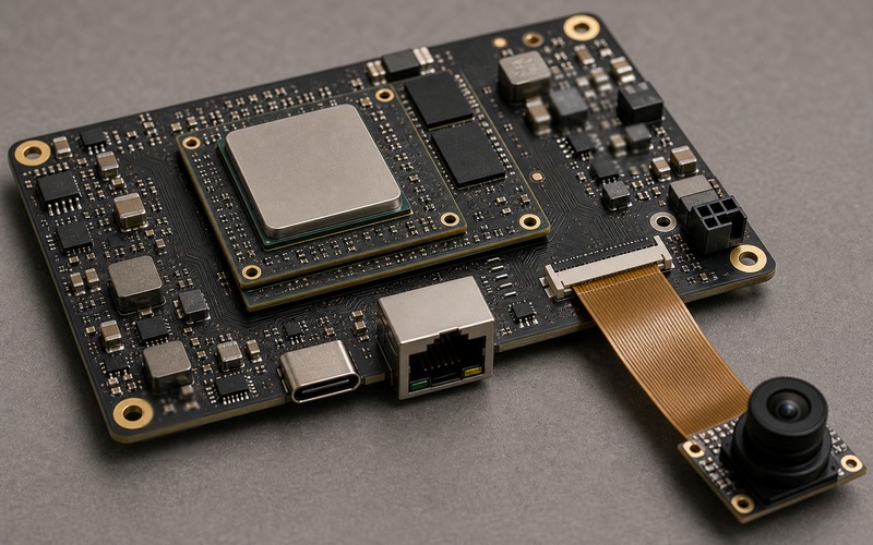
Interfaces constrain thermal placement. Camera FPC, antenna feed, Ethernet magnetics, USB connector, battery cable and field wiring may force hot blocks away from the neat thermal center. The layout must respect signal and mechanical requirements while preserving a heat exit.
Choose Passive, Forced or Chassis Cooling Early
Passive cooling uses copper, heat spreaders, pads, enclosure metal and natural convection. It has no moving part and suits sealed products, but it needs surface area and temperature margin. The enclosure may become the heatsink, which brings touch temperature and mounting conditions into the design.
Forced cooling buys margin by moving air, yet it adds noise, dust intake, power draw, inlet and outlet geometry, reliability concerns and service questions. A blower that works in an open prototype may lose flow once cables, filters and walls are installed.
Chassis cooling conducts heat into a metal case, rail or mounting plate. It can be strong in industrial boxes, but it depends on mounting torque, flatness, interface material and installation. A wall-mounted box on an insulating surface may not behave like the lab sample.
The cooling choice also affects sourcing. A thermal pad, blower, heatsink, metal extrusion, adapter and power module all become supply items with tolerances. The approved substitute list should include thermal effect along with fit and price.
Leave Margin for the Parts Around the Processor
The processor is rarely the only limit. Memory can heat under bandwidth load. Storage can warm during writes. A radio can add heat during upload. A camera sensor can drift when its local board area warms. A PMIC or buck regulator can reach its thermal limit before compute throttles.
Analog and sensor sections may need distance from hot copper. A temperature sensor, reference, microphone, pressure sensor or optical path can be pushed out of tolerance by local heating. The power and thermal ceiling should include accuracy, noise and processor survival together.
Battery-powered equipment adds another boundary. Charge current, cell temperature, regulator efficiency and sleep current change the allowed duty cycle. A product can meet inference power for a short period and still miss runtime or charge-temperature targets.
Derating should be applied to nearby components as well. Capacitor life, inductor temperature rise, connector current rating, FET loss, fuse behavior and adhesive aging can all set a lower ceiling than the processor data sheet suggests.
A good release package marks each heat-sensitive neighbor and states what is protected: timing margin, analog accuracy, image quality, wireless performance, storage reliability, enclosure temperature or long service life.
Validate With the Final Workload
Thermal validation should run the final workload, not a convenient proxy. The product may need live camera input, model execution, radio traffic, storage writes, display load and charging at the same time. Each active block changes both power and heat location.
Log power rails and temperature together. Input voltage, input current, regulator temperature, compute temperature, board temperature, enclosure surface and performance state should be captured during warm-up and steady operation. A temperature graph without workload state can hide throttling.
Measure in the final mechanical state. Lid installed, screws torqued, cables attached, antenna placed, gasket compressed, mounting bracket fitted and expected orientation used. Small mechanical differences can change airflow and conduction.
Test multiple samples and build conditions. Solder voiding, pad placement, enclosure flatness, screw torque, copper tolerance and adapter variation can move the result. A one-sample pass is not enough for a product that will ship with normal production spread.
Inspect after the run. Discolored areas, softened adhesive, shifted pads, loose fasteners, hot connectors and warm neighboring sensors reveal risks that a single processor temperature cannot show.
Set the Boundary for Substitutions
Once the ceiling is known, component substitutions need a thermal and power boundary. A regulator alternate must meet electrical needs, efficiency at load, package heat path, copper requirement and current limit behavior. A compute-module alternate must fit the adapter rating, spreader, firmware policy and sustained workload.
Pin compatibility does not guarantee thermal compatibility. A device can share pads and still move heat through a smaller exposed area, draw higher current during bursts or require different airflow. The substitute should be tested against the same workload and enclosure.
For long-life products, record the acceptable power envelope, package options, heat-spreader contact, regulator loss limit, allowed adapter range, thermal interface rule and any firmware throttling policy. Buyers can then check exact part numbers without turning every shortage into a redesign.
If a new part changes the ceiling, mark it as an engineering change. It may still be usable, but it should not enter the routine alternate list until thermal and power validation has been repeated.
Edge AI Release Checklist
Before release, check enclosure material, volume, vent path, surface temperature, power input, input protection, sustained power, peak power, regulator losses, copper area, thermal vias, spreader path, airflow or chassis path, workload and neighboring heat-sensitive parts.
Then verify the built product with the final workload. Record power and temperature together, watch throttling, check enclosure surfaces, inspect regulators and memory, and repeat across enough samples to see assembly spread.
The design is ready when the chosen compute, power tree and enclosure can hold the promised workload with defined margin. If the product depends on an open bench, perfect airflow or one carefully built sample, the ceiling has already rejected the design.