Working Junction Temperature From Power and Thermal Resistance
Junction temperature becomes useful only when the number is tied to a heat path that exists on the board. A part can report a die reading, a package can list a resistance, and a data sheet can show a test board, but the product still has its own copper, enclosure, airflow and workload.
The calculation starts with the heat the device must shed. It then follows that heat through silicon, package, solder, copper, thermal vias, spreader, enclosure and air. Each boundary has uncertainty, so the result should be treated as a release estimate that needs measurement, not as a lab truth written into the design forever.
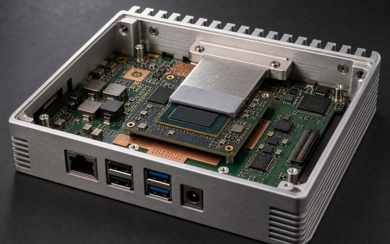
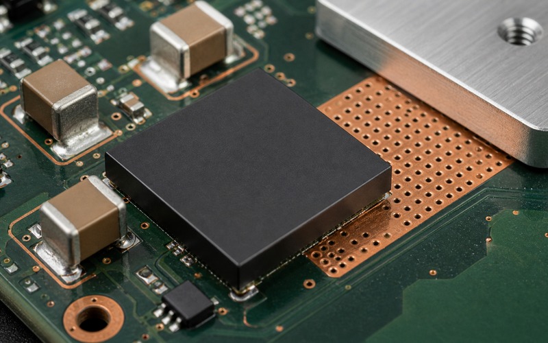
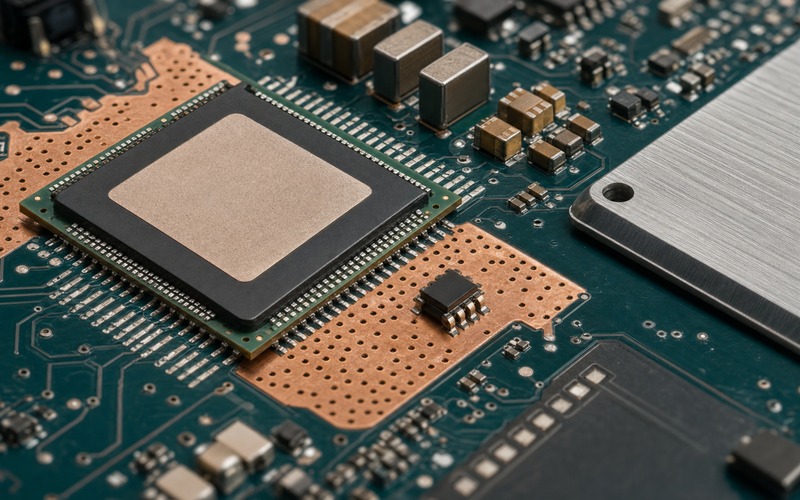
A strong review shows the hot package, copper area, thermal via field, nearby temperature-sensing point and metal spreader as one chain. If one part of that chain is guessed, the junction number may look precise while the product still throttles.
The article stays at board-level selection. It does not replace silicon thermal modeling. It gives engineers and buyers a shared way to judge whether a power device, processor, regulator or replacement part can survive the board it will be fitted to.
Start With the Heat the Device Must Shed
Power becomes heat through losses. In a processor, the heat depends on workload, clock plan, voltage, active memory traffic and accelerator duty cycle. In a regulator, it comes from conduction loss, switching loss, driver loss and the conditions around the inductor, diode or power stage. A thermal calculation that begins with a single catalog number misses the design case.
Use the load profile that can hold long enough to warm the product. A short benchmark may create a high peak, while a sustained camera, radio, motor or neural-inference load can decide steady temperature. The number that matters for a wearable, gateway, industrial sensor or compact AI board is the power that remains after warm soak, enclosure heating and control-loop behavior are included.
Do not hide losses outside the named part. A processor rail may move heat into the regulator beside it. A power module may send heat into the inductor, copper pour and shielding. A sensor hub can warm a reference or analog front end. Junction temperature belongs to a layout, so the heat source list should include nearby parts that raise the local board temperature.
For a replacement review, keep the same workload and rail conditions. A pin-compatible device with higher leakage, lower efficiency or different thermal pad construction can raise the heat even when the electrical function still passes. Power is the input to the thermal calculation, so sourcing approval must keep it under control.
Keep the Temperature Reference Points Separate
Ambient temperature, internal air temperature, board temperature, case temperature and junction temperature are different reference points. Mixing them turns a calculation into a guess. The designer must state which point is measured, which point is assumed and which point is being estimated.
Ambient is the air outside the product or test setup. Internal air can be higher inside a closed enclosure. Board temperature may rise near regulators, processors, memory or radios. Case temperature can mean a package top, a metal spreader, a shield or the outer housing. Junction temperature is inside the silicon and is usually inferred unless the device reports a calibrated internal sensor.
The common formula uses temperature rise equal to power multiplied by thermal resistance. The reference point decides the resistance path. Junction-to-ambient, junction-to-case, junction-to-board and junction-to-top cannot be swapped without changing the physical route. A low junction-to-case value does not help if the case has no effective path into a heatsink or enclosure.
Measurement points need the same care. A small temperature sensor near a hot device can be valuable, but it is not the junction. An infrared reading can miss emissivity and hidden copper. A thermocouple can change contact or read a nearby metal part. These readings should anchor the model, not pretend to replace it.
Read Thermal Resistance as a Stack
Thermal resistance is a stack of restrictions, not a magic property of one package. Heat may leave the die through a package paddle, a solder joint, a copper island, thermal vias, inner planes, a heat spreader, a pad, enclosure metal and moving or still air. The limiting section can sit anywhere in that chain.
A board with sparse vias can waste a low package resistance. A thick copper pour without a path to air can store heat and warm neighboring devices. A large spreader without pressure or a short conduction path can look helpful in a drawing and fail in the product. The stack must be read from the hot spot outward.
Package options change the stack. A QFN or DFN with an exposed pad depends on solder coverage and via design. A BGA may spread heat through balls and planes. A module with an integrated metal base may need a controlled interface to chassis. The same power number can lead to different junction temperature because the heat exits the package in different ways.
Thermal resistance values from data sheets depend on test boards, copper area, airflow assumptions and measurement methods. They are useful for comparison and early screening, but they cannot prove a compact product. If the product board has less copper, different layers, a nearby warm inductor or a sealed housing, the final path must be measured.
The stack view also protects substitutions. A part with the same pinout and electrical rating may move heat through a smaller pad, a different mold compound or a higher case path. If purchasing treats thermal resistance as a footnote, the substitute can pass functional test and fail during warm operation.
The release review should draw the path in words before doing math. State where heat is made, where it enters the board, how it spreads, which metal or air path removes it and which section has the tightest margin. That short map prevents a single resistance number from hiding an incomplete design.
Use the Formula With Limits in View
The simple estimate is temperature rise equals power times thermal resistance. It is a good screening tool when the reference point and path are correct. It is weak when the power changes with temperature, airflow changes with enclosure position or several heat sources warm the same copper area.
Start with a conservative local temperature. If the product sits in a warm cabinet, sealed box, vehicle roof, handheld enclosure or outdoor node, external ambient may not be the temperature seen by the package. Use the temperature around the part or build a margin from measured internal air and local board readings.
Then add the rise for the chosen path. For a device using junction-to-board resistance, the board temperature near the thermal pad matters. For a device tied to a spreader, the spreader path and interface must be part of the estimate. For a part cooled by airflow, fan curve, duct restriction, dust and orientation can change the result.
Keep the calculation directional. Do not use a generous junction-to-ambient number from a large open test board to approve a dense closed design. Do not use a package-top reading as proof of junction margin unless the package path has been correlated. Do not mix a peak workload with a steady resistance value without judging time.
The formula can still guide decisions. It can show that a thicker interface has no margin, that an extra watt will push a regulator over the limit, that more copper or vias are needed, or that a package with a better exposed pad is safer. The value comes from comparing choices under the same assumptions.
Handle Transient and Steady Heat Differently
Thermal systems have time constants. A short power burst may raise junction temperature before the case or board looks warm. A long load can heat the board, enclosure and air until the entire product sits at a higher starting point. Both cases can matter.
Processors often run bursty workloads. A neural accelerator, image pipe or radio can create short spikes, then idle. The silicon may tolerate brief rise if firmware controls duty cycle and the package path can absorb it. A regulator feeding a constant load may face a slower but stricter steady-state limit.
Use transient data when available, but do not stretch it beyond the conditions behind the curve. Pulse length, duty cycle, copper area and board stack affect the result. If a curve comes from a test board that does not match the product, it can still guide trend, but it should not close the release.
Steady-state testing remains necessary for compact products. After warm soak, the copper around the device can start hotter, nearby sensors can drift, memory can warm, and enclosure surface limits can become the controlling item. A part that passes a short bench run may fail the long customer workload.
Measure the Board You Built
A good measurement plan combines internal readings, board points and external surfaces. Use the device thermal sensor when it exists, measure the package or spreader, place a small sensor near the hot area, watch the regulator or power stage, and record the enclosure surface that a user or cabinet will see.
The test setup must match the intended product state. Enclosure closed, cables installed, display on, radio active, battery charging, motor duty cycle, mounting position and airflow can all change temperature. If the setup is easier than the product, the test creates false margin.
Measure power at the same time. Temperature without power cannot validate thermal resistance. Rail voltage, current, workload state and throttling state should be logged with temperature. If firmware reduces frequency or duty cycle during the test, record that behavior instead of reporting only the cooler final temperature.
Look for gradients. A hot copper island beside a cool package top can mean the heat path is leaving through the board. A hot package top with cool copper may mean the pad or solder path is weak. A warm enclosure with a hot die may mean the final air path is limiting. The pattern often tells more than one temperature number.
Repeat across samples. Assembly torque, solder voiding, copper tolerance, pad placement, board thickness and enclosure fit can move the result. A design with two degrees of margin in one sample may have no margin in a normal production spread.
Set Derating and Substitute Boundaries
A released part should not run at its absolute limit during the expected workload. Derating gives room for ambient variation, dust, aging, enclosure change, silicon spread and measurement uncertainty. The margin should be stated in engineering terms, not hidden as a vague comfort factor.
For a processor, the boundary may include workload, voltage, clock, package option, allowed throttling point, copper area, spreader contact and firmware thermal policy. For a regulator, it may include input voltage, output current, switching frequency, inductor loss, copper area, airflow and nearby heat sources.
A substitute must stay inside that boundary. Same footprint, same pinout and same output current do not guarantee the same junction temperature. Check package thermal pad, resistance values, efficiency curve, leakage, switching loss, allowed board copper and any change in recommended layout.
If the substitute needs less copper, higher airflow or a different heat spreader, it is not a drop-in thermal substitute. It may still be usable after layout or enclosure review, but it should not enter the approved list as a routine alternate.
Purchasing can support the boundary by requesting the exact package suffix, package drawing, lifecycle status, thermal data and any layout notes before approving a change. Engineering should provide the workload and thermal limit that define the acceptable range.
Junction Temperature Release Checklist
Before release, record heat source power, workload, reference temperature, resistance path, board copper, thermal vias, package style, local air, nearby heat sources, enclosure path, spreader contact, measurement points and derating margin.
Then test the built product. Log power and temperature together, warm soak the enclosure, check transient and steady behavior, watch for throttling, inspect hot neighbors and repeat across enough samples to see assembly spread.
The calculation is ready when it matches the board closely enough to guide a real decision: accept the part, change the package, add copper, change airflow, improve the spreader or reject a substitute. If the number cannot drive that decision, it is only arithmetic.