Jetson Orin Nano as an Entry Edge Inference Box
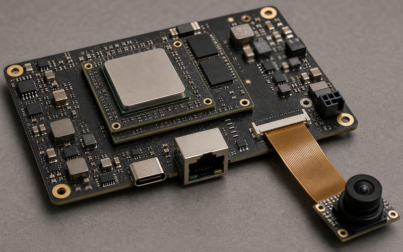
A Jetson Orin Nano class module can make a first edge inference box feel close to finished. The compute block, memory, accelerator, software base and board-to-board connector are already packaged into a small module, so the team can move from model testing to a boxed prototype faster than with a processor placed directly on a custom PCB.
That shortcut has a boundary. The product is still decided by the carrier board, power entry, external interfaces, camera routing, storage method, cooling hardware, enclosure, recovery path and supply plan. If those parts are treated as a loose accessory around the module, the box may work on a bench and fail as soon as cables, heat, dust, firmware updates and field service enter the picture.
The useful selection question is not whether the module can run a model. It is whether the surrounding hardware lets the same model run in the final box with stable I/O, a clean power path, predictable temperature, recoverable software and approved substitutes for the parts that are not on the module.
Start With the Module Boundary
The module boundary is the reason to use this class of platform. It moves the hardest processor layout, memory bus and high-speed internal routing away from the first custom board. The carrier board can then focus on power input, I/O, mechanical mounting, camera entry, network connection, service access and protection parts.
That boundary also fixes many choices. The connector pitch, module footprint, mounting hole pattern, heat spreader height, supported interface set and power sequencing rules become design inputs. The carrier should be drawn around those fixed points early, rather than trying to make an existing generic board accept the module after enclosure and connector positions are already chosen.
Review the exact module revision, the approved carrier reference design, the thermal contact area and the interface pins that are used in the product. Leave unused pins controlled as recommended by the vendor documentation. A first box does not need every interface populated, but every brought-out interface needs a reason, protection, clearance and test method.
This boundary review also keeps the project from overusing the development kit as a product blueprint. A vendor development board is built for access, measurement and flexibility. A saleable box needs fewer sockets, firmer mounting, clearer cable exits, controlled recovery access and a bill of materials that can be purchased and assembled repeatedly.
Treat the Carrier Board as Product Hardware
A carrier board is not a passive adapter. It is the product's electrical and mechanical contract with the outside world. It has the power entry, USB or Ethernet connector, camera connector, display header, reset path, status LED, storage socket, fan header, debug port and mounting outline. Those parts decide how the module behaves once the product leaves the lab.
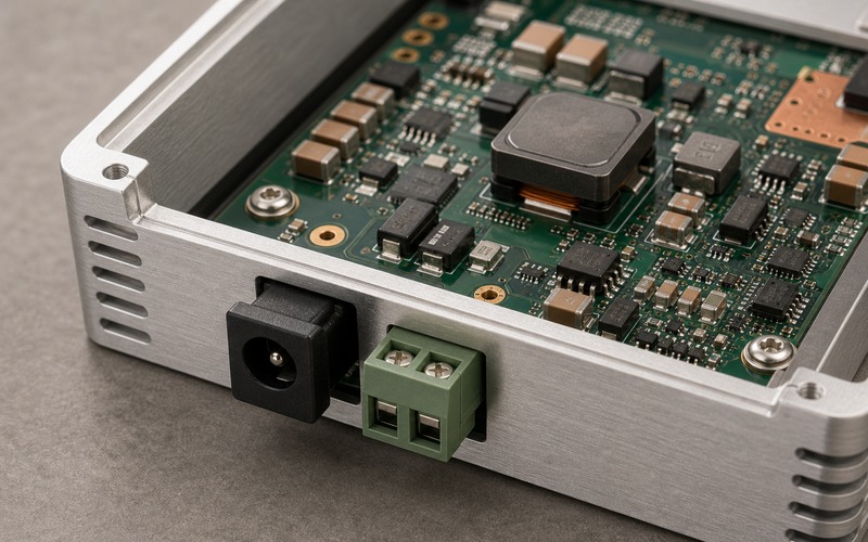
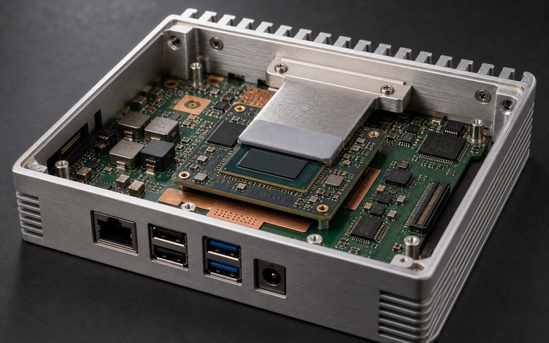
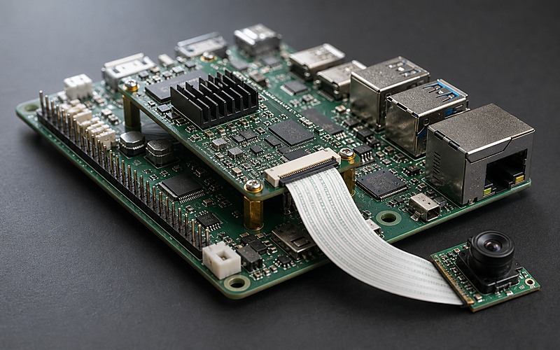
Place board-edge connectors where cables can exit without folding into the heatsink, lid, antenna space or camera ribbon. Keep the FPC connector near the board edge if the camera leaves the box, and avoid routing sharp bends through a service path. The Ethernet jack, USB connector, power barrel or terminal input must face an accessible wall, not the middle of the board.
The carrier also decides manufacturability. A reliable build needs clear keepouts around the module connector, assembly access for screws or standoffs, a controlled height stack, enough copper for the power path and test pads for rails and reset signals. A development carrier can tolerate awkward jumper access; a product carrier cannot.
Add measurement points while the board still has space. A rail-good signal, reset line, boot strap, fan tachometer, camera power rail and service UART can save hours during bring-up and production repair. Those points do not have to become customer-facing ports, but they should be accessible enough for the factory to confirm a failure without removing the module.
Keep Camera and Display Interfaces Honest
Vision boxes fail early when the image path is treated as a cable detail. Camera links, display outputs and high-speed USB lanes are layout items, not decorative headers. The routing length, impedance, connector orientation, shield termination, cable strain relief and nearby switching noise shape whether the link is stable across units.
For a camera-heavy box, decide how many sensors are real product requirements and which ones are bench conveniences. Each camera connector adds FPC handling, ESD exposure, mounting tolerance, optical alignment and cable service risk. A single reliable camera path usually beats a carrier filled with unused camera sockets.
If the box needs display output for setup or service, separate that need from the inference workload. A service display connector can be accessible during installation and absent from the sealed product, while an operational display interface needs mechanical support, EMI review and power budget of its own. Treat each external port as a routed system with protection and a test plan.
Cable choice should be part of the same review. A short bench ribbon and a production cable routed through a hinge, gasket or camera mount behave differently. The connector latch, cable stiffness and insertion direction should be checked with the real optical bracket and lid installed.
Size Power and Cooling Around the Box Duty Cycle
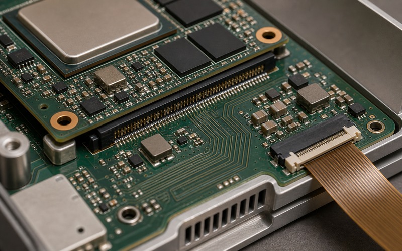
The entry module lowers design risk, but it does not remove the box-level power and cooling check. The regulator losses, power connector rating, input protection, cable drop, fan or heatsink choice and aluminum wall contact still decide whether the module holds the expected workload. A module that is calm during a short demo can warm the enclosure during continuous capture and inference.
Build the power tree from the field input inward. Check adapter range, reverse protection, surge or hot-plug behavior, fuse or eFuse choice, buck regulator headroom, inductor current, output capacitance and load transient behavior. The module supply should be measured at the module pins during boot, camera start, network activity and sustained inference rather than only at idle.
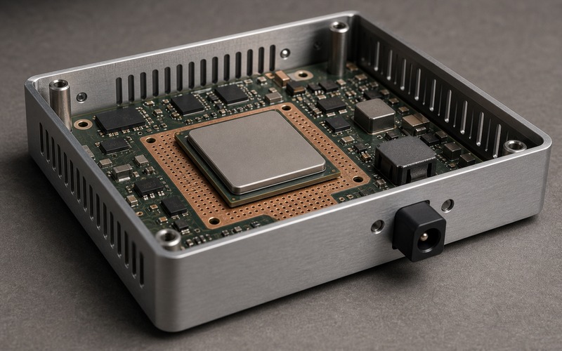
Cooling should be selected with the same duty cycle. A small fanless metal box can work when heat has a clean path from module to spreader to chassis. A plastic enclosure or dust-heavy environment may need a different mechanical answer. The first carrier should leave space for a thermal interface material, mounting pressure control and a later heatsink or airflow change if test data calls for it.
The first prototype should log rail voltage and temperature while running the same model, camera resolution and network behavior expected in use. Short peak tests are useful for bring-up, but they do not reveal heat soak, enclosure warming or a regulator that loses margin after the board has been working for a long period.
Plan Storage, Boot and Recovery
An edge inference box is judged by recovery as much as by first boot. The storage device holds the operating image, model files, logs, configuration and update state. If the storage choice is weak, a power interruption or failed update can turn a field unit into a return.
Decide whether the product uses removable storage, soldered flash, eMMC on the module, external NVMe, or another supported boot path. Each option changes service access, vibration risk, thermal load, write endurance, cost and security handling. A removable card is convenient for a prototype but may be the wrong service model for a sealed box. A soldered device can be stronger mechanically but needs a programming and recovery route.
Add a practical recovery path before the enclosure is frozen. That can mean a service header, recovery button, protected USB access, dual image policy, watchdog, power-cycle behavior and a documented way to restore a corrupted image. The board should let production verify the image, serial number, MAC address, camera identity and I/O function without a special bench setup that cannot be repeated at scale.
Protect External Ports and Cables
Every cable entering the box brings electrical and mechanical risk. Ethernet, USB, camera FPC, power input, GPIO and debug access can carry ESD, cable stress, ground shift, moisture paths and user mistakes. The module may be well designed, but the carrier board is where the outside world reaches it.
Put ESD protection near the connector, route return paths cleanly and keep high-speed pairs away from noisy switching nodes. Place common-mode parts, magnetics, power protection and filtering where the connector geometry allows short, understandable paths. A protection part placed far from the entry point may pass the schematic review and still fail the event path in the real layout.
Mechanical protection matters too. Connector shells, latch access, FPC bend radius, screw posts, gasket lines and cable clamps should be reviewed with the enclosure model. A neat PCB can become fragile when the cable exits at a hard angle or when the lid presses on a ribbon cable.
Check the Software Image and Production Path
The module choice influences software, but the product still needs a production image. Drivers, camera configuration, network setup, watchdog policy, logging, model version, security settings and update behavior have to match the hardware that will ship. A bench image with development packages and loose credentials should not become the factory image.
Keep the bill of materials tied to the software assumptions. If a camera, storage device, Ethernet PHY, USB hub, fan controller or power monitor changes, the software image may also need a device tree, driver, calibration file or test update. The substitution review should include software impact along with footprint and price.
Production test should exercise the real path: boot, rail health, camera stream, network link, storage write, inference load, thermal sensor, recovery trigger and final power cycle. The goal is to catch weak assembly, wrong cable orientation, marginal rails and image mismatch before the box leaves the line.
Keep the production image narrow. Remove unused development services, lock down default credentials, record the installed model version and keep a repeatable method for loading configuration. When a field unit is returned, the team should be able to tell whether the issue came from the carrier, the module, the software image, the camera path or the installation environment.
Set the Boundary for Approved Alternatives
A first edge box is often built quickly, then asked to live longer than its prototype assumptions. Record what can change and what cannot. The module SKU, carrier connector, power IC, inductor, camera connector, Ethernet magnetics, storage device, oscillator, thermal pad, fan and enclosure hardware each need a substitution rule.
Some replacements are electrical. Others are mechanical or software-linked. A camera connector with the same pin count may have a different latch direction. A storage device can match capacity and still change endurance or boot behavior. A fan can fit the holes and still shift acoustic, dust and lifetime risk. The approved list should name the checks that protect the product rather than naming the part family alone.
For purchasing, keep module availability, carrier-only parts and enclosure hardware separated. If the module is fixed but the carrier connector, storage socket or power entry changes, the box still needs a regression check. If the module revision changes, treat the carrier and image as linked items until the boot, camera, network and thermal tests pass again.
Entry Edge Box Release Checklist
Before treating a Jetson Orin Nano class build as a product, review the module revision, carrier board layout, connector access, camera routing, power tree, cooling path, storage plan, recovery method, external protection and factory test flow together.
The box is ready for release work when the final enclosure can run the target workload, recover from a failed update, survive cable handling, pass functional test with the planned image and accept only substitutes that have been checked against electrical, thermal, mechanical and software conditions.