Depth From a Time of Flight Sensor for Vision AI
How a ToF sensor adds depth to vision AI by controlling emitter timing, optics, field of view, reflectance, ambient light, calibration and board layout.
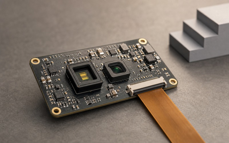
A vision model that only sees brightness must infer distance from clues that can lie. Texture size, shadow, blur and perspective help, but they can change with lighting, lens choice and object finish. A time of flight sensor adds another input: a distance estimate tied to emitted light and a measured return.
Depth does not make a vision product immune to error. It adds a second measurement channel with its own optical, electrical and mechanical limits. The board still needs an emitter, a receiver, timing control, filtering, clean power and calibration data that survive the move from bench sample to field assembly.
The useful question is not whether ToF gives depth. It is whether the depth map is stable enough for the model decision being made. Presence detection, hand tracking, obstacle sensing, shelf monitoring and people counting all stress the sensor in different ways.
Depth Is a Measurement Channel, Not a Decoration
A ToF front end measures distance by comparing emitted light with returned light. Some devices use direct timing, while others infer phase shift from modulated light. The product team does not need to turn every buyer review into an optics lecture, but it does need to know which assumptions sit behind the depth number.
The reported distance depends on emitter power, receiver sensitivity, integration time, timing accuracy, lens field, target reflectance and ambient light rejection. The model may receive a depth frame, a confidence map, a point cloud or a processed presence flag. Those outputs are not interchangeable.
If the model only needs to know whether a hand is close to a panel, a coarse range window may be enough. If it needs to separate a box from a shelf edge, depth noise, lateral resolution and multipath reflections become part of the model input.
Match the Range to the Real Scene
Every ToF sensor has a range where its result is useful. Below that range, the optical path may be saturated, clipped or affected by package crosstalk. Beyond that range, the return can fall into noise, ambient light or algorithmic guesswork.
The design should start with scene distance, not headline range. A smart lock that reads a hand near the handle, a robot that avoids chair legs and a shelf sensor looking across a narrow bay each need a different range window. If the depth requirement is vague, the selected module can pass a demo and fail the product.
Range must be checked with the real surface. White card tests are convenient, yet many field targets are black plastic, fabric, skin, glass, polished metal, cardboard or curved packaging. A target that reflects well in visible light may return little near-infrared signal, and a glossy target may send light away from the receiver.
The approval record should state near limit, far limit and the surfaces used in validation. A substitute sensor or lens should be judged against those scene limits rather than against a catalog number alone.
Emitter and Receiver Geometry Set the Depth Quality
The emitter and receiver do not see the scene from the same point. Baseline, lens field, package window and board height shape what part of the returned light reaches the receiver. A compact module can hide this detail, but the mechanical design still affects it.
Keep the optical windows clear. A gasket, bezel, adhesive, cover glass or decorative black window can clip the field or add internal reflection. If the enclosure window shifts across production tolerance, the depth frame can lose one edge before the color image shows a problem.
Placement also affects multipath. Light can bounce from a nearby wall, glossy faceplate or angled housing and arrive at the receiver after a second path. The sensor may report a distance that sits between the target and the reflection. For model input, that can look like a soft false surface.
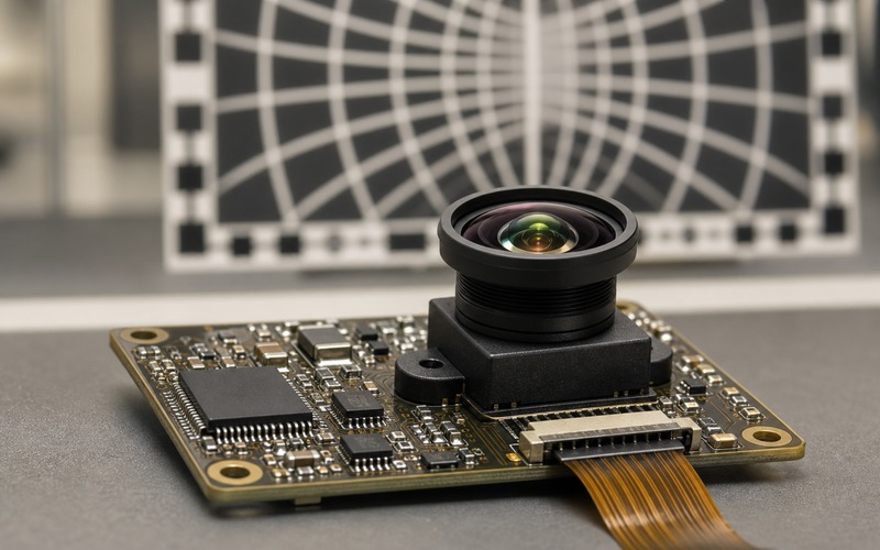
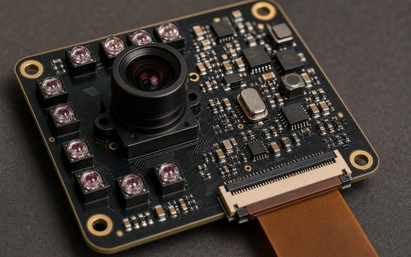
A useful board review checks the sensor package, keepout area, cover window, FPC exit and nearby tall parts in one view. The flex cable should leave through the board edge without folding across the optical field or pressing on the module.
Ambient Light and Reflectance Decide Confidence
Sunlight and strong indoor lighting raise the optical noise floor. The ToF receiver can use filters and modulation to reject part of that light, but the margin is not infinite. A design that works in a dim lab can lose confidence near a window or under direct industrial lighting.
Reflectance creates another gap between a clean demo and a finished product. A matte gray block may return a stable signal. Black rubber, shiny metal, transparent plastic or a wet surface can produce weak or confusing returns. Depth confidence should be treated as a signal, not ignored.
The model should know when depth is missing or weak. Feeding a low-confidence depth value as if it were reliable can be worse than using no depth at that pixel. Some systems mask weak depth, some add confidence as a channel, and some make a separate rule for close-range trigger decisions.
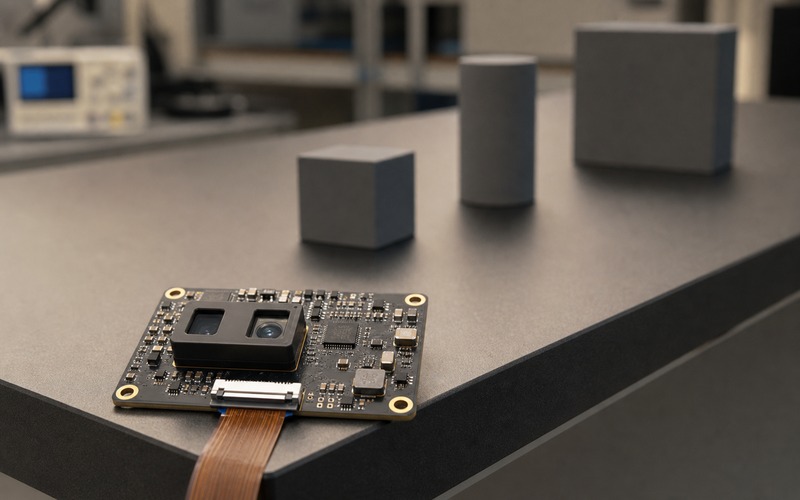
Validation frames should include bright light, low light, dark surfaces, glossy surfaces, edges, holes and angled planes. The target list should look like the product environment, not a lab exercise built from clean blocks.
Resolution and Field of View Need the Same Review
A depth frame has spatial resolution. If the target occupies only a few depth pixels, the model may see a flickering blob rather than a stable object. Increasing the color camera resolution will not fix a depth sensor that cannot resolve the shape needed for the decision.
Field of view alignment matters. The depth sensor and image sensor may not see the same scene. Lens offsets, module tilt and different fields can leave parts of the color frame without depth. If the model fuses color and depth, registration error becomes a data problem.
A narrow ToF field can work for a doorway, a handle or a fixed inspection area. A wide robot or people-counting application may need broader coverage and more careful edge behavior. The correct choice depends on the action tied to the depth value.
Timing, Frame Rate and Motion Are Part of the Input
Depth data arrives at a rate. If the ToF frame is slower than the color frame or delayed by processing, a moving target can appear in one position in color and another in depth. A model that fuses both streams needs timestamps, alignment rules or a defined trigger sequence.
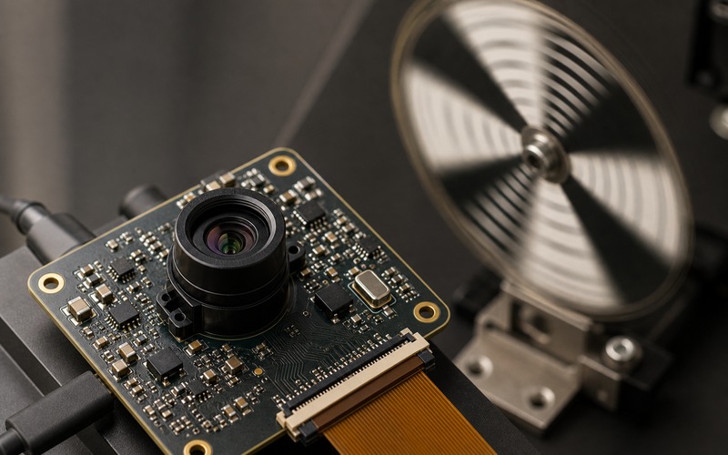
Motion can also lower confidence. A hand moving through the field, a rotating object or a robot passing a reflective edge can create mixed returns. Exposure time, modulation cycle and processing filters decide whether the depth map follows the object or smears it.
When the depth result controls safety or motion, latency should be measured at the system output rather than at the sensor interface alone. The time from emitted light to model decision includes sensor exposure, readout, bus transfer, host scheduling and inference.
A production test can include a moving target if the product uses depth on moving objects. Static blocks catch range offset; they do not reveal timing lag.
Calibration Is a Production Item
ToF depth accuracy depends on calibration. Offset, temperature, optical crosstalk, lens window, emitter output and processing tables can all affect the final number. A module may ship with factory calibration, but the finished product can add its own optical stack and mechanical tolerances.
If the enclosure window, gasket or cover material changes, the depth offset can change. If the module height changes, field clipping can change. If the board is reworked and the sensor tilts, near-field depth can drift. These are production issues, not lab curiosities.
The release file should state which calibration data is fixed in the module, which is measured in final assembly and which is checked by sample validation. If a second-source module is allowed, its calibration path must be reviewed before it is treated as a drop-in replacement.
Temperature also belongs in the check. Emitter output, receiver response and timing circuits can shift as the board warms. A short warm-up test at expected product temperature can reveal range drift that a room-temperature snapshot hides.
Power and Layout Shape the Optical Result
The emitter can draw pulsed current, and that current returns through the same board that holds the receiver and host interface. Weak decoupling, long current loops or shared impedance can move noise into the sensor supply or timing reference.
Keep high-current emitter paths compact. Give the receiver and timing circuits clean local decoupling. Separate noisy switching nodes from the optical module where the layout allows it. The result is an optical measurement, but the failure can start as a board-level power problem.
Thermal placement matters as well. A hot regulator next to the ToF package can shift temperature across the module. A high-current emitter without copper area can run hot and lose output margin. The board review should include copper, vias, airflow and enclosure contact.
The connector path is also a mechanical input. A flex cable that bends over the module can shade the aperture or press on the package. A board-edge connector with a clean exit path is easier to assemble and inspect.
Use Depth Where It Changes the Decision
Depth is valuable when it removes an ambiguity that color or grayscale cannot handle. It can separate a real object from a printed image, keep a trigger inside a physical zone, reject background motion, estimate object height or support obstacle avoidance.
It is less useful when the decision depends on texture, color marking or fine printed detail. In those cases, depth may support segmentation or gating, but it does not replace the image sensor. The model architecture should reflect that split instead of treating depth as a magic feature.
The input format should be decided early. Some teams use depth as another image channel. Some use it to crop a region before inference. Some keep it outside the model and use it as a rule check around the model output. Each route has different data, timing and validation needs.
Validation Before Release
A release-ready ToF design should be tested with the selected sensor module, emitter settings, lens window, enclosure, FPC path, power rails and firmware settings. Capture scenes at near and far limits, under strong ambient light, with dark and reflective surfaces, across temperature and with moving targets if the product sees motion.
Record raw depth, confidence, processed depth and the final model decision. The failure cases matter: missing depth at edges, false surfaces from reflections, confidence drop near sunlight, frame mismatch during motion and offset after warm-up.
The purchasing approval should lock more than the package. It should lock optical field, wavelength or modulation assumptions, calibration path, connector orientation, host interface, power limits and validation surfaces. A pin-compatible swap that changes any of those points can change the model input. That is why ToF belongs in the same review as the sensor, optics, firmware and model data.