How Rolling Shutter Smears a Fast Moving Object for a Vision Model
Rolling shutter is a timing behavior that becomes visible when the scene moves during the readout of a frame. The sensor does not capture every row at the same instant. It starts at one side of the array, reads row after row, and finishes later. A static object still looks normal. A fast object can appear bent, stretched, leaning or broken into shapes the model never saw during training.
For a person viewing a video, the distortion may look like blur or a strange slant. For a vision model, it changes geometry. Edges move, keypoints shift, object boxes drift and small features may land in the wrong place. A detector that learned a straight label edge, a round wheel, a vertical package side or a square marker can see a different object when readout timing smears the frame.
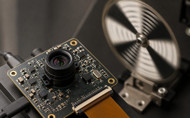
The issue is not limited to high-end cameras. Small embedded sensors, low-cost camera modules and compact AI devices often use rolling shutter because it saves cost, power and silicon complexity. That can be acceptable, but only if the motion, exposure and model loop are checked as part of the sensor selection.
Rolling Shutter Is a Line Timing Problem
A rolling shutter image is assembled over time. The top row may represent an earlier instant than the bottom row. If the object moves sideways, rotates or vibrates during that interval, each row records a slightly different position. The resulting image contains a time sweep, not a single frozen moment.
The important number is the row-to-row and frame readout time rather than frame rate alone. A camera can advertise 60 frames per second while each frame still takes a long time to scan. If the object crosses a meaningful distance during that scan, the model receives a distorted shape.
This is why two sensors with the same resolution and frame rate can behave differently. Readout architecture, blanking, exposure mode, data format and interface speed all affect the time between the first and last row. The selection review should ask how long the array needs to deliver one frame under the chosen mode.
Mode tables deserve careful reading. Cropped modes, binned modes and reduced resolution modes can shorten readout, but they can also change field of view, sampling density and model input scale. The right mode is the one that preserves the feature size while keeping row timing inside the motion margin.
Motion Direction Decides the Error Shape
A fast object moving across the rows often leans or stretches. A rotating fan, wheel or gear can turn into curved blades. A vibrating product can produce wavy edges. A conveyor object can look longer, shorter or shifted depending on scan direction. These changes matter because the model is reading shape, not intent.
The same physical speed can be safe in one direction and risky in another. Motion parallel to the readout direction may change length. Motion across the readout direction may skew the object. Rotation can combine both effects. A board-level test should include the real mounting direction of the camera, because rotating the module can rotate the failure mode.
If the product can be installed in more than one orientation, the review should include those orientations. A model trained with one camera angle may fail when a field unit mounts the camera upside down or sideways and the rolling shutter distortion changes direction.
Distance changes the error as well. A small angular movement near the camera can sweep across many pixels, while the same physical speed farther away may move across fewer pixels. The test should describe distance, lens field and expected speed together, because the model only sees pixel displacement.
Exposure Time and Readout Time Are Different
Short exposure reduces motion blur, but it does not remove rolling shutter geometry error by itself. Exposure controls how long each row collects light. Readout controls when each row is captured relative to the other rows. A short exposure can create a sharp object that is still slanted because rows were sampled at different moments.
This distinction is easy to miss in a lab. Engineers may reduce exposure, add light and see a sharper image, then assume the motion problem has been solved. The model may still see a skewed boundary or shifted feature. The test should separate blur from readout distortion by measuring object position across the frame.
Illumination can help if it supports shorter exposure or synchronized capture. It can also create banding or partial exposure when pulsed light does not align with sensor timing. LED drivers, PWM dimming and mains-powered lighting should be checked with the same sensor mode the product will use.
For a device with its own light source, record pulse timing, rise time, current limit and duty cycle. A short bright pulse can freeze blur, but if the pulse overlaps only part of the rolling scan, the frame may show brightness bands or a half-lit target. That artifact can be as harmful to the model as geometric skew.
Global Shutter Is Not a Free Upgrade
A global shutter exposes the frame at one time, so it protects object geometry during fast motion. This makes it attractive for conveyors, robotics, vehicle vision, barcode capture, rotating machinery and high-speed inspection. It can reduce training burden because the model sees shapes closer to the physical target.
The tradeoff is design cost. Global shutter sensors may have different pixel efficiency, noise, die area, package options, interface needs, lens constraints and price. A product with slow motion and controlled lighting may pass with rolling shutter after validation. A product with fast edges, precise localization or rotating parts may need global shutter from the first prototype.
The choice should be made from measured model performance. Compare rolling and global shutter samples if the application sits near the boundary. Check false detections, missed detections, localization error and confidence stability instead of judging by image appearance alone.
There is also a middle path. Some rolling shutter sensors offer faster readout modes, smaller regions of interest or trigger controls that reduce the error for a defined scene. Those modes should be treated as approved operating conditions. If firmware later changes the mode, the motion validation should be repeated.
Frame Rate Does Not Guarantee Model Timing
Frame rate says how often frames are delivered, but it does not guarantee the time structure inside each frame. A higher frame rate can reduce object displacement between frames, yet the frame can still contain row skew. The model may receive more distorted frames per second rather than cleaner input.
The full timing chain includes exposure, row readout, data transfer, image signal processing, buffer handling, pre-processing and inference. If any part drops frames, repeats frames or changes latency, the model output can become unstable. Timestamping helps only when the software and control loop use those timestamps correctly.
Interface margin also matters. MIPI lane errors, weak connectors, long FPC cables or processor load can add frame faults that look like model problems. A rolling shutter review should include the camera link and processing path instead of treating the sensor as an isolated component.
For trigger-based products, the output action has its own deadline. A sorter gate, motor stop, alarm or robot pick point may need the object position at a precise moment. If the image was scanned over time and then processed later, the control code needs to know which point in time the reported position represents.
Training Data Must Match the Captured Geometry
A model trained on clean static images can perform well in evaluation and fail on a moving product. The data gap is geometric. The model learned one shape, then the camera delivers a slanted or stretched version of that shape. Augmenting the training set can help, but it is better to know whether the distortion is stable and bounded.
Collect sample frames with the real sensor, lens, illumination and mounting position. Include the expected speed range, vibration, rotation and exposure settings. Run those frames through the model and inspect the errors. If the model misses the same edge or shifts the same box repeatedly, the sensor timing is part of the cause.
Training changes cannot rescue every hardware choice. If a safety function, sorting action or robotic motion depends on precise position, the input geometry may need to be protected at the sensor level. That may mean global shutter, stronger lighting, a different lens, shorter readout mode or a changed mounting angle.
Keep a small validation set for future changes. If a camera module, lens, firmware mode, light driver or cable changes later, run the same moving-target images through the model again. This prevents a purchasing substitution from silently changing the timing profile that the model depends on.
Board and Connector Details Still Matter
Rolling shutter is an optical and timing topic, but the PCB can still make it worse. Clock jitter, supply noise, weak grounding, poor decoupling and high-speed routing errors can disturb frames. A camera module that looks stable on a bench can become unreliable when the FPC bends, the enclosure closes or a motor turns on.
Connector direction should be reviewed in the mechanical assembly. The FPC or camera connector should face the board edge or cable exit route. A cable forced toward the board center can bend sharply, lift contacts or change the camera angle. Those small mechanical shifts can alter focus, field of view and vibration response.
Keep the approved sensor mode, cable length, connector height, regulator choice, clock part and firmware settings in the BOM record. A later substitute camera module may stream frames, yet it can change readout time, lens field, filter stack or connector mechanics enough to move the model input.
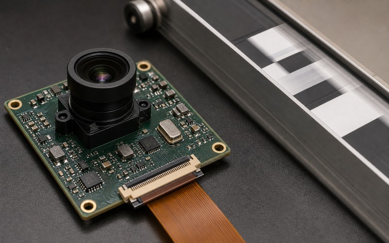
The production test should include a motion or timing proxy when the application depends on fast objects. A static focus chart catches lens and sharpness problems, but it will not reveal row skew. A small rotating target, moving bar or triggered light pattern can give the factory a practical way to detect the wrong sensor mode or module variant.
Validation Checklist Before Release
Before release, record the selected sensor mode, exposure time, frame readout time, interface data rate, lens, illumination state, mounting direction, cable route and processing latency. Capture image sets at the fastest expected object speed and at the edge of the lighting range. Run the model on those image sets rather than approving the camera from a still photo.
Measure the errors that matter to the product: detection rate, false detection, box shift, keypoint error, count stability, trigger timing and control-loop response. Repeat the test after warmup, after cable flex and with nearby motors or lighting drivers active if those conditions exist in the device.
A rolling shutter sensor can be a good choice when the motion case is understood and the model is trained and tested against the same geometry. It becomes risky when row timing is ignored. The safe selection record states what motion was tested, which sensor mode passed, what lighting was used and which changes require retest before purchasing or production release.