Which Image Sensor Specs Matter for a Vision Model
A vision model reads the world through the sensor, lens, light source and the timing path that delivers frames to the processor. If that input changes, model behavior changes with it. A camera chosen for a human viewer can look attractive in a brochure and still feed unstable data to a detector, classifier or counting model.
The useful sensor question is practical: what will the model need to recognize, at what distance, under what light, while the product is moving or still? The answer decides which sensor specifications deserve attention. Resolution, pixel size, optical format, shutter type, interface, dynamic range, noise, package and connector details all matter only when they affect the data reaching the model.
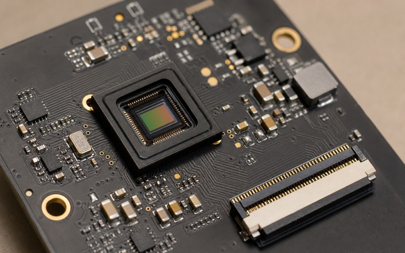
A good selection review treats the sensor as part of an input chain. The part number is only one line. Lens field of view, illumination, exposure control, frame timing, board routing, supply noise and production substitution rules can change the final image before software sees it.
Start With the Scene the Model Must Read
Begin with the target, background and distance range. A barcode reader, a people counter, a defect camera and a low-power presence sensor do not need the same input. The size of the feature to be recognized should drive the pixel count across that feature, the field of view and the exposure time. Without that scene definition, resolution and frame rate become loose catalog choices.
Write down the smallest feature the model must separate from the background. For a screw head, solder bridge, face outline, label edge or object boundary, define the physical size, distance, motion speed and lighting range. This turns the sensor decision into an engineering check rather than a guess based on megapixels.
The scene also defines how stable the input must be. A model trained with evenly lit lab images may fail when a glossy surface, window reflection or dim corner changes the data. Sensor choice should leave enough exposure, noise and dynamic range margin for those expected scenes.
Resolution Is Useful Only After Target Size Is Known
Resolution helps when it puts enough pixels on the feature the model has to read. Extra pixels can help crop, align and detect small details, but they also raise bandwidth, memory, processing load and storage needs. A higher pixel count can slow the pipeline if the processor, interface or model size cannot handle the data rate.
Calculate pixels per target before choosing a part. If the object occupies a small part of the frame, the model may need a wider resolution or a narrower lens field. If the object fills the frame, a lower resolution with larger pixels may perform better in real light. The image sensor and lens must be selected together.
Resolution also affects production test. If the model depends on a narrow focus zone, a lens shift or sensor tilt can reduce usable detail even though the raw pixel count is unchanged. The review should include focus tolerance, assembly stack-up and any calibration required at the factory.
Pixel Size and Optical Format Set the Light Budget
Pixel size is a light-collection decision. Larger pixels collect more photons during the same exposure time, which can reduce noise in dim scenes and allow shorter exposure under motion. Smaller pixels can give more sampling points in the same die area, but the optics and lighting must support them.
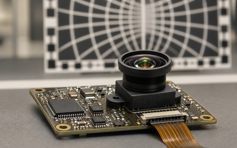
Optical format links the sensor to lens choice. A sensor with a larger active area may need a larger image circle and a lens that keeps sharpness across the required field. A mismatch can create corner shading, distortion, color shift or blurred edges that the model was not trained to handle.
The light budget should include enclosure glass, filters, dust, aging and LED drive limits. If the product sits behind tinted plastic or works from a small battery, sensor sensitivity and lens transmission can matter more than headline resolution.
Shutter Choice Changes Motion Error
A rolling shutter reads the frame line by line. It can be fine for static scenes, slow movement and cost-sensitive modules, but fast motion can bend edges or shift object geometry. A global shutter exposes the whole frame at once and can protect shape when parts move on a conveyor, a robot arm sweeps through the scene or a vehicle camera sees vibration.
The choice is about model geometry rather than image appearance to a person. Motion distortion can move a bounding box, hide an edge or shift a key feature. If training data uses clean static images and the product sees motion, the shutter behavior should be tested early.
Exposure time, illumination pulse width and synchronization also matter. A rolling shutter with controlled light and timing may pass in some products. A global shutter without enough light can still deliver noisy frames. The correct choice comes from the motion and light case together.
Interface and Frame Rate Shape the Processing Path
The sensor interface decides how data reaches the processor. MIPI CSI-2 gives high data rate with controlled routing rules, while parallel buses and lower-speed serial links may fit simpler devices. The board must support lane count, clocking, impedance, connector quality and cable length if a remote camera module is used.
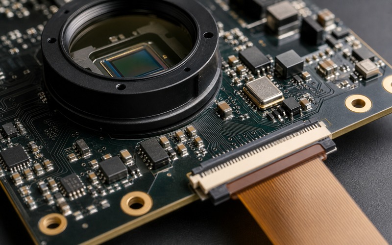
Frame rate should be chosen from the model loop, not from a headline maximum. A model that triggers an action within 100 ms may need a camera, exposure, transfer, pre-processing and inference chain that can meet that time. A high sensor frame rate does not help if the processor drops frames or the interface cannot move raw data without errors.
Data format also changes the path. RAW output gives the processor control over image signal processing, but it adds bandwidth and software work. YUV or RGB output may simplify integration, but it may hide sensor tuning decisions inside the module. Check which format the model expects and how the product will keep that format stable through revisions.
Buffer depth, frame sync and error recovery belong in the same review. A camera link that works during a short lab capture may show dropped frames after cable flex, warm startup or processor load. The model team should know whether missing frames are ignored, repeated or timestamped, because each behavior changes the data stream feeding the decision.
Dynamic Range and Noise Decide What the Model Sees
Dynamic range sets how much bright and dark detail can survive in one scene. This matters for doorways, reflective metal, outdoor devices, backlit displays and inspection stations with shadows. If highlights clip or dark regions sink into noise, the model may miss the feature even though the image looks acceptable at a glance.
Noise is also data. Shot noise, dark current, column noise, supply ripple and analog gain can change the texture of the frame. A classifier trained on clean images may react badly to noisy low-light frames. A detector may produce unstable boxes when edges dissolve into noise.
Review gain range, exposure control, black level behavior, temperature effect and fixed-pattern correction. Then test sample images across the real light range. The decision should be based on frames the model will process, not on a single well-lit bench photo.
Lens, Filter and Illumination Are Part of the Sensor Choice
The sensor cannot be selected alone. Lens focal length, aperture, distortion, focus range, filter stack and illumination set the image before it reaches the silicon. A sensor with good numbers can fail if the lens blurs the edge of the field or the IR filter changes color response in the target scene.
Check whether the model depends on color, edge position, texture, depth cue or contrast. Color work needs a stable spectral path and white-balance behavior. Dim object detection may need wider aperture, stronger illumination or a sensor with better low-light performance. High-speed capture may need more light rather than more pixels.
Production assembly should be included. Threaded lens holders, fixed-focus modules and glued optics each create different focus and alignment risk. If the model is sensitive to small blur changes, the approval plan should include focus test limits and a way to catch lens tilt or contamination.
Package, Connector and Supply Details Affect Production
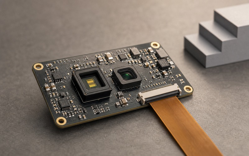
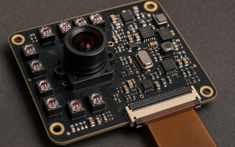
The sensor package, board footprint and connector are production choices as much as electrical choices. Bare sensor packages, small camera modules and FPC-connected assemblies carry different handling, inspection and sourcing risk. The connector should face the board edge or cable exit direction so the camera can be assembled and serviced without forcing the cable through the board center.
Power integrity deserves a separate check. Image sensors can be sensitive to analog rail noise, digital rail droop and clock jitter. Local decoupling, regulator choice, ground return and high-speed routing affect the frame even if the sensor powers up and streams data.
Substitution risk should be written into the BOM record. If a second module uses a different lens, sensor revision, IR filter or connector height, it can change the model input. Approved alternatives should be tested with the same images, same firmware settings and same factory checks before a buyer treats them as usable.
Mechanical stack-up should be measured with the real enclosure. Sensor tilt, lens holder height, gasket pressure, glass thickness and cable bend radius can shift focus or block a corner of the image. Those details may sit outside the sensor data sheet, but they decide whether the selected part can be built repeatably.
Prototype Validation Checklist
Before freezing the design, capture frames from the selected sensor across distance, light, temperature, motion, exposure and focus limits. Run those frames through the model instead of judging them through a viewer alone. Record which settings and part suffixes were used, including lens, filter, module, connector and firmware configuration.
Check the board side as well. Confirm interface margin, connector insertion direction, clock quality, regulator noise, decoupling layout, thermal path and mechanical stack-up. A camera that streams on a bench can still fail when the cable bends, the enclosure closes or a warmer board shifts focus.
A clean image sensor choice gives engineers and buyers the same rule set: which part is approved, which lens and connector belong with it, what data proves model performance, and what changes require retest. That record protects the vision input from silent substitutions that look harmless on a BOM but change the image seen by the model.
The final review should include sample images, model metrics, raw capture settings, layout notes, connector orientation, optical stack details and the approved purchasing suffix. If a future substitute changes any of those lines, it should return to engineering review before it enters production.