How Lens Distortion Bites a Vision Model
How lens distortion changes geometry for vision AI, from field of view and edge pixels to calibration, module assembly, compute cost and approved substitutions.
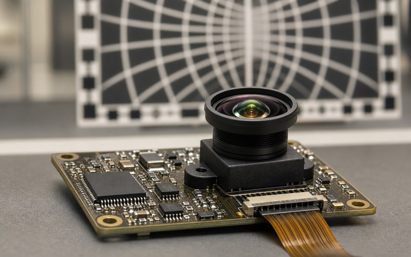
A vision model learns from geometry as much as from color and texture. When the lens bends straight lines, stretches the image edge or changes the apparent size of objects, the model receives a scene that is shaped by optics before it reaches the image sensor. The error can look small in a viewer and still change a detection boundary, a distance cue or a feature that the model has learned to trust.
Lens distortion is often discussed as an image quality issue, yet it is also a data integrity issue. A wide angle lens can help a compact device see more of the scene, but the outer field can bend, stretch and soften details. A model trained on one optical shape may react poorly after a lens change, a module swap or a housing window change.
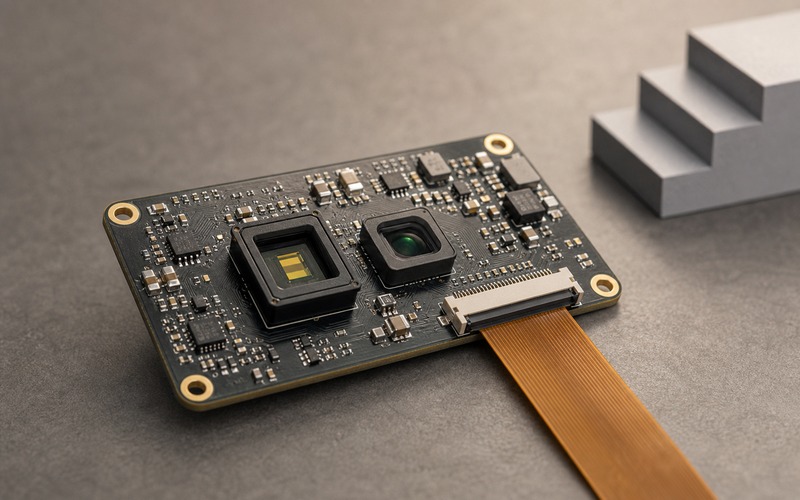
The selection review should connect lens field, sensor format, module assembly, calibration data and compute budget. Treat the lens as part of the model input path, not as a camera accessory added after the board is finished.
Distortion Is a Geometry Error
Barrel distortion pushes straight lines outward. Pincushion distortion pulls them inward. Complex wide angle optics can mix several error shapes across the frame. The model does not see those labels. It sees shifted pixels, curved object edges and changed distances between features.
A human viewer may accept a bent line near the border. A model looking for a package edge, lane mark, face outline, meter pointer or connector row may treat the same bend as a real shape. That is why a lens change can move accuracy even when resolution, sensor and lighting stay fixed.
The data sheet may list total distortion or a distortion curve. That number should be tied back to the field area used by the model. If the model crops the center, edge distortion may matter less. If it tracks hands, people, shelves, robots or objects entering from the side, the edge behavior belongs in the release gate.
Field of View Changes the Training Problem
A wider field of view captures more of the product scene, but it changes scale. Objects near the frame edge can become smaller, stretched or tilted compared with objects in the center. Training data collected with a narrow lens may not represent the same scene after a wider module is fitted.
The first check is the real viewing task. A door camera, warehouse shelf sensor, robot navigation camera and wearable camera all ask the lens to solve a different problem. More field can add context, or it can add background clutter that raises false detections.
Focal length, sensor diagonal and lens image circle should be reviewed as a set. A lens that appears compatible by thread, package height or module outline can still miss the intended sensor format or create dark corners. Mechanical fit is not the same as optical fit.
When the application depends on object size or position, keep a fixed test chart or scene record for each approved lens. The scene record should include center, corner and side targets, not a clean central shot alone.
Edge Pixels Carry Higher Risk
The outer field is where distortion, vignetting, blur and color shift often meet. A model that uses edge pixels for entry detection, people counting or obstacle warning is exposed to the weakest part of the optical path.
Edge detail can be useful, but it needs proof. Capture objects crossing the frame boundary, small parts near a corner and lines running close to the side. If the model loses a target at the same position where the lens stretches or darkens the image, the issue is optical as much as algorithmic.
The enclosure can make the edge worse. A cover window, adhesive bead, bezel lip or gasket can clip the field. If the window is curved or tilted, it can add its own distortion on top of the lens. The final product stack should be used for validation rather than an open bench module.
Calibration Must Travel With the Lens
Distortion correction works when calibration data matches the optical path. Intrinsic parameters, distortion coefficients, sensor alignment and focus distance need to belong to the lens, sensor and assembly method being shipped.
A factory camera module may include its own calibration route. A board-level lens and sensor design may require production calibration, sample calibration or a locked mechanical stack. The choice should be written down before purchasing approves a second lens source.
Calibration data also needs a storage and firmware path. If the host cannot load the right parameters, or if the module vendor changes optics without a visible orderable code change, the model can receive uncorrected or wrongly corrected frames.
Keep the calibration decision close to the bill of materials. A substitute lens is not approved by thread, height and price alone. It must keep image circle, field of view, distortion shape, focus range, coating behavior and calibration path inside the accepted range.
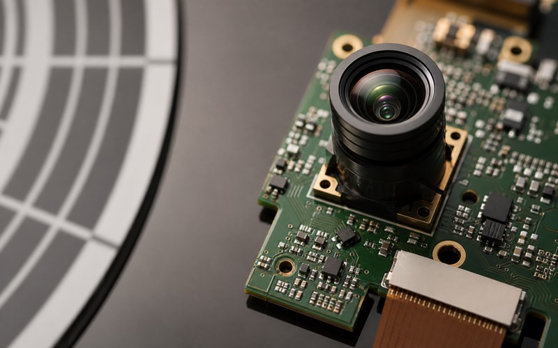
Module Assembly Can Move the Error
Lens distortion is measured through an assembly. Tilt, decenter, focus drift and sensor placement can move the error from symmetric and predictable to uneven across the frame. Two modules with the same nominal lens can behave differently if the assembly process changes.
Look for mechanical references that hold the optical axis. Threaded lens holders, molded barrels, adhesive locks, shim height and board flatness all matter. A small tilt can shift corner sharpness and make the correction table less effective.
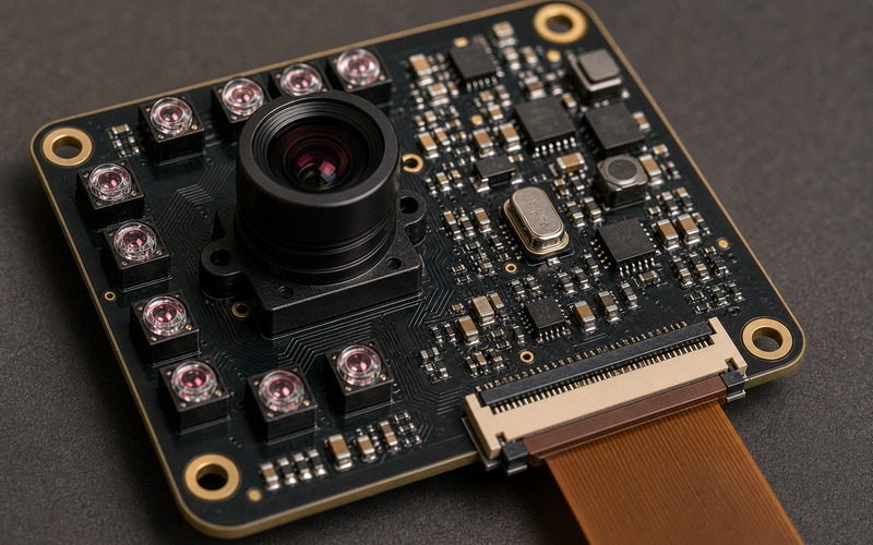
The FPC path and connector orientation also need attention. A flex cable should leave toward the board edge without bending over the optical module or pulling the board. Connector direction that fights assembly can lead to stress, tilt or rework marks near the camera area.
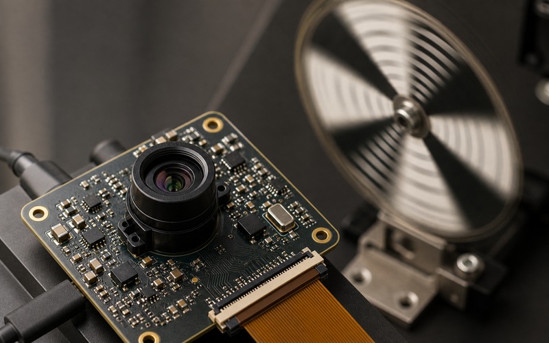
Incoming inspection can include a quick corner chart, focus check and field alignment capture. That is often more useful than a visual check of the lens barrel alone.
Distortion Correction Has a Compute Cost
Software can remap the image, but remapping costs memory bandwidth, processing time and sometimes image sharpness. On a small edge device, the correction path can compete with ISP work, neural inference and display or network transfer.
Correction can be done before the model, inside preprocessing or through training that accepts the lens shape. Each route changes latency and validation. If correction happens before inference, the corrected frame should be what the model sees during training and test.
Some products can leave mild distortion in place if the model is trained and validated on that exact lens. Other products need straight geometry, such as measurement, pointer reading, shelf alignment or lane tracking. The decision should be tied to the task, not to a general rule.
The release test should measure frame rate with correction enabled, not with a clean demo path. If the correction step forces frame drops, a lower distortion lens may be the better part even when its optical format is larger or its cost is higher.
Lighting and Windows Add Optical Error
A lens is rarely exposed directly to the scene in the final product. Clear plastic, glass, IR filter stacks, privacy covers and protective windows can all change the image. They can add flare, ghosting, color shift, reflection or extra distortion.
For a vision model, flare or reflection can become a false feature. A curved window can move geometry across the image. A low grade cover can soften corners and reduce the details that the model uses for classification.
Lighting should be reviewed with the lens. Wide angle lenses can catch stray LEDs, enclosure reflections and bright sources outside the intended region. If the device uses IR lighting, coating and filter choices need to match the wavelength as well as the visible image.
Validate with the final window material, final black mask, final adhesive and final lighting placement. A bare module image is useful for debug, but it is not enough for release approval.
Validation Images Need Corners and Edges
A distortion review fails when all samples are centered. The validation set should include straight lines near the border, small objects crossing the edge, angled planes, close objects, far objects and high contrast details near each corner.
Capture raw frames, corrected frames and model output for the same scenes. If correction creates missing pixels, crop changes or resampling softness, the model output should be checked again. The corrected image can look cleaner while losing detail that mattered to inference.
The test should include multiple modules from normal sourcing. A single golden sample can hide assembly spread. If the camera is replaceable or sourced from multiple vendors, each approved route needs the same chart and scene record.
Keep the image evidence with the component approval. When a later purchasing change is proposed, the comparison can start from known optical behavior rather than from a generic claim of compatibility.
Substitute Lens and Module Review
A substitute lens or camera module should be checked against the model input, package and connector together. Field of view, distortion curve, focus range, sensor format, chief ray angle, IR filter, window stack and calibration data all affect what the model receives.
If the host firmware expects one calibration file and the substitute needs another, the change is not drop-in. If the image circle changes, the same sensor may gain dark corners. If the field widens, objects at the side may become smaller and less stable.
Supply planning should list approved optical alternatives with their validation evidence. The review should state which items are interchangeable in production and which require retraining, recalibration or a firmware update.
This prevents a purchasing shortcut from becoming a model accuracy issue. It also gives engineers and buyers the same language for discussing lens availability, module lifecycle and replacement risk.
Release Checklist
Before release, confirm the lens, sensor, module outline, FPC exit, cover window and lighting are the same as the validation build. Check center and corner images, raw and corrected frames, field of view, focus distance, distortion behavior, frame rate and model output.
The approval file should include optical parameters, calibration ownership, correction location, storage path for parameters, allowed substitutes and the scenes used to qualify them. It should also state when a lens or module change requires new model validation.
A vision model can survive distortion when the error is known, stable and represented in its data path. It struggles when optics change silently. Lens selection should stay in the same review as the image sensor, firmware pipeline and purchasing approval, because all of them shape the pixels that reach the model.