What Infrared Lighting Does for Night Vision AI
Night vision AI is not created by the model alone. The model receives whatever the sensor, lens, filter and lighting system put into the frame. In a dark scene, infrared illumination can turn an empty black image into usable structure, but it can also create glare, uneven brightness, hot pixels, motion artifacts and a data distribution that differs from training images.
Infrared light is attractive because many image sensors remain sensitive beyond visible red. A product can light the scene in a band a person barely sees or cannot see, then let the camera read shape, texture and reflectance. That makes it useful for presence detection, access control, security cameras, low-light inspection and robot navigation.
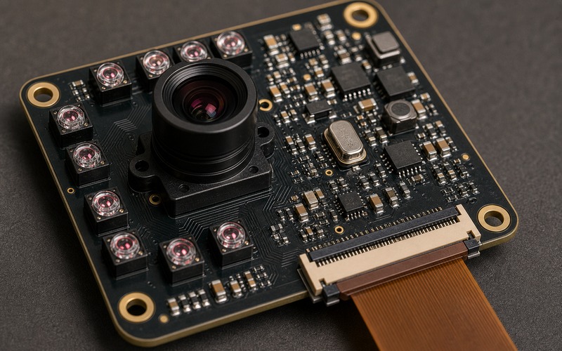
The design decision is larger than choosing an LED. Wavelength, emitter angle, placement, drive current, thermal path, lens filter, exposure setting, power noise and validation images all decide whether the model sees stable night data or a scene full of artifacts.
Infrared Lighting Is Part of the Vision Input
A visible-light camera depends on ambient light. A night vision camera supplies part of its own scene. That means the lighting pattern becomes part of the model input. If the illumination changes across production lots, board revisions or enclosure options, the model can see a different world even when the sensor part number remains the same.
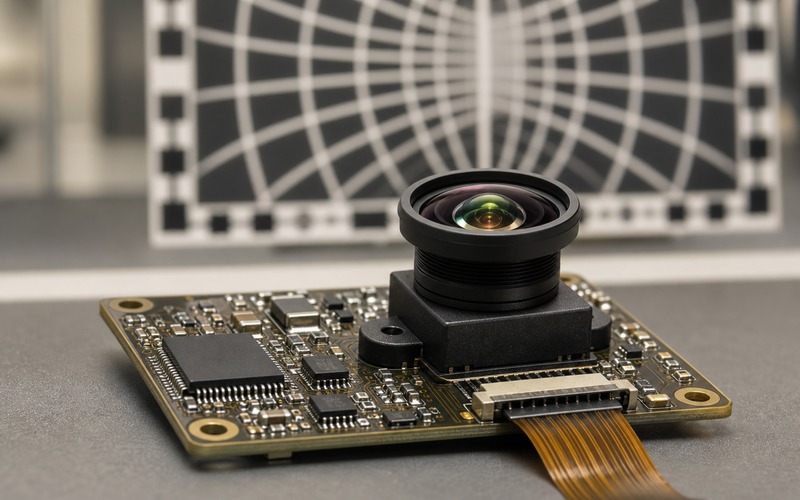
Treat infrared emitters as part of the imaging chain. The LED package, lens, beam angle, output power, drive waveform and distance to the target shape contrast before the image reaches the sensor. A model trained with one lighting geometry may fail when an alternate LED creates a different hotspot or shadow.
The review should include the sensor and illumination together. A sensor with good low-light sensitivity can still produce poor night frames if the light is too narrow. A strong emitter can still fail if the target reflects unevenly or the lens picks up internal flare.
Choose Wavelength Before Choosing the LED
Common night vision designs use near-infrared bands such as 850 nm or 940 nm. An 850 nm emitter often gives stronger sensor response and longer range with many silicon sensors, while a faint red glow may be visible at the emitter. A 940 nm emitter is less visible to people, but the sensor response and range can be lower.
The correct wavelength depends on the product. A security camera may accept a small visible glow for range. A wearable, meter, access device or indoor sensor may prefer lower visible emission. The enclosure window, IR pass filter, sensor quantum efficiency and eye-safety requirement should be checked before the LED is selected.
Wavelength also affects materials. Plastics, coatings, glass, dust, fabric and skin reflect infrared differently from visible light. If the model reads color or texture in daytime and shape at night, the training and validation sets need to cover that spectral shift.
The supply record should lock the wavelength range as well as the package size. Two LEDs with the same body can sit at different peak wavelengths or have different spectral spread. A camera that works at 850 nm may lose margin with a 940 nm substitute, and a dark cover window that passes one band may attenuate another.
Place Emitters to Avoid Lens Flare
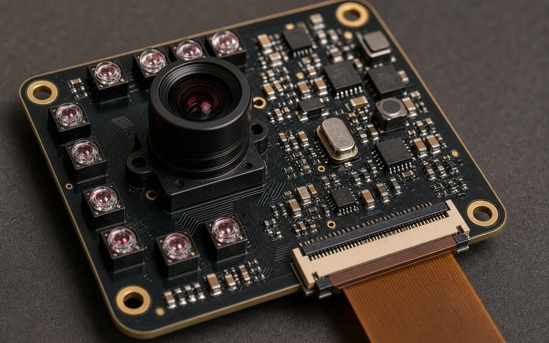
Emitter position decides whether the sensor sees a lit target or stray light. LEDs too close to the lens can reflect from the cover glass, lens barrel, bezel or enclosure window. That reflection can wash out the center of the image or create bright rings that the model mistakes for scene features.
Separate the emitters from the optical path when the mechanical design allows it. Use baffles, dark surfaces, angled windows or lens shields where reflection is likely. If the product has a transparent cover, test the cover in place because bench results without the cover can hide flare.
Placement also sets uniformity. A tight LED cluster can leave a hotspot near the center and dark corners. Distributed emitters can improve coverage, but they add board area, routing, current balance and thermal concerns. The image should be checked at the near, middle and far distances the product will see.
Coaxial lighting, side lighting and ring lighting create different shadows. A face access product, a barcode reader and a robot gripper may need different shadow behavior. The image set should include the real mounting height and target angle so the model is trained against the lighting geometry it will see after assembly.
LED Drive Sets Brightness, Heat and Stability
Infrared brightness comes from current, duty cycle and thermal conditions. A higher current can extend range, but it can heat the LED, shift output, stress the driver and inject noise into nearby camera rails. If the device is battery powered, lighting current may dominate the night-mode power budget.
A regulated LED driver is usually easier to control than a loose resistor path when brightness and repeatability matter. Current tolerance, PWM frequency, pulse width, soft start, thermal foldback and fault behavior should be recorded. The model depends on consistent frames, so lighting variation becomes an input stability problem.
Thermal coupling should be reviewed on the PCB. Several IR emitters near the lens can warm the board, shift lens focus slightly, raise sensor noise or reduce LED output over time. Copper area, vias, duty cycle and enclosure airflow decide whether the night image stays stable during a long run.
Aging should be part of the margin. LED output drops with time and temperature. If the first prototype only passes with maximum current and gain, the design may lose range after field use. Leave enough current, exposure or optical margin so the model does not depend on a brand-new emitter at room temperature.
Exposure and Gain Must Follow the Light
Adding infrared light does not remove the need for exposure control. If the camera uses automatic exposure, a bright near object can drive exposure down and make the background disappear. If the exposure is fixed, a close reflective target can clip while a far matte target stays dark.
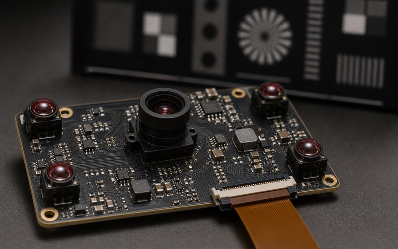
Analog gain and digital gain change the noise pattern the model sees. More gain may reveal a feature, but it can also amplify dark current, fixed-pattern noise and power ripple. The exposure strategy should be tested with the same LED current and wavelength planned for production.
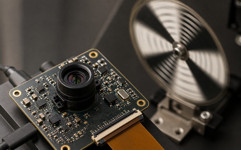
For pulsed illumination, timing matters. The LED pulse should overlap the sensor exposure in the intended mode. With rolling shutter, a poorly timed pulse can light only part of the frame or create bands. With global shutter, the pulse window is easier to control, but driver rise time and synchronization still matter.
Day and night switching also needs a rule. Some products keep a color camera path by day and an infrared path by night. If the model uses the same labels across both modes, the validation set should include the transition region where ambient light is low but not fully dark. That is often where exposure, white balance and IR contribution fight each other.
Uniformity Matters More Than Peak Brightness
A bright center spot can look impressive in a sample image while reducing model performance. The model may learn a center-heavy scene and fail when the target appears in a dark corner. A lower peak level with wider, smoother coverage can be a better input for detection and tracking.
Uniformity should be measured across distance and field of view. Check corners, edges, reflective objects, black objects and objects close to the enclosure window. If the lens has vignetting or the LEDs have narrow beams, the error can stack up and leave the model with weak detail at the edge.
The validation image set should include bright, matte, dark, angled and reflective targets. A night vision system that works on a white card may fail on black plastic or a shiny metal part. Infrared reflectance does not always match what a person sees under visible light.
Filter, Lens and Sensor Sensitivity Must Match
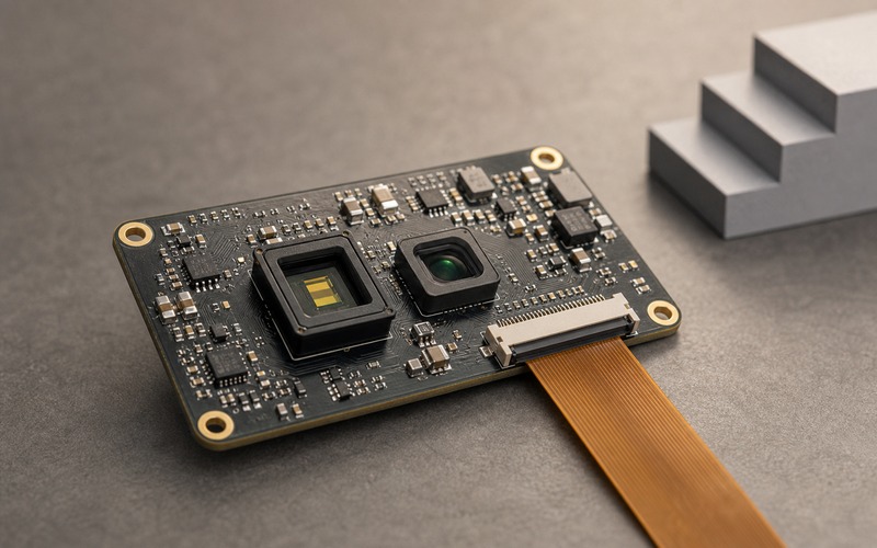
The sensor must be able to see the selected infrared band. Some camera modules include an IR-cut filter for daylight color accuracy. That filter can block the light needed for night operation. Other designs use switchable filters or dedicated monochrome sensors to improve night sensitivity.
The lens matters as well. Focus can shift between visible and infrared wavelengths. A lens that is sharp in daylight may soften at 850 nm or 940 nm unless it is designed for the band. If the model depends on fine edges, night focus should be checked rather than assumed.
The optical stack also includes the enclosure window. A black-looking plastic window may pass infrared, or it may absorb the chosen band. Coatings, adhesives and gasket materials can create reflections. Test with the final stack so the model sees production-like frames.
If the device uses a visible-light mode as well, filter strategy affects both sides. A fixed IR-pass design may lose color information in daytime. A fixed IR-cut design may fail at night. A switchable filter adds moving parts, driver needs and test points, but it can protect both modes when the application needs them.
Power Noise and Layout Can Change the Frame
IR LEDs switch significant current. That current can disturb the camera if the driver shares weak rails, long return paths or poor decoupling with the image sensor. Ripple, ground bounce and EMI can appear as bands, flicker, frame noise or unstable black level.
Keep LED current loops compact and away from sensitive analog sensor nodes when the layout allows it. Give the camera rails clean regulation and local decoupling. Place driver heat where it does not warm the lens barrel or sensor package. Route FPC connectors toward the board edge so the cable can exit without bending across emitters or the optical path.
A substitute LED, driver or camera module should not be approved from pin fit alone. It can change output power, wavelength, beam angle, pulse timing, thermal behavior or sensor response. Those changes can shift the night input enough to require model retest.
Incoming inspection can include a small optical check when the product depends on night images. A current measurement proves the LED circuit is alive, but it does not prove beam angle, wavelength or reflection behavior. A short dark-box image test can catch the wrong LED lens, wrong window material or incorrect driver setting before the board reaches final assembly.
Prototype Validation Checklist
Before release, capture night image sets with the selected sensor, lens, filter, LED wavelength, drive current, exposure setting, enclosure window and cable routing. Include near and far targets, dark and reflective materials, moving objects, warm-up time and low battery or weak supply conditions if those apply.
Run the frames through the model and record detection rate, false detections, box shift, confidence stability, trigger timing and failure cases. Compare images with LEDs off, nominal current, reduced current and high-temperature operation. That shows whether the model depends on a narrow lighting condition.
A good infrared lighting design gives the model a repeatable night scene. The approval record should state the wavelength, LED package, driver settings, optical stack, exposure mode, power limits and substitute-part rules. If any of those lines changes later, the night vision validation should be repeated before production release or purchasing substitution.