Free Shipping Over$200

- Products
- Marking
- Alternative

MP2315 for a Compact Buck on Support Circuitry
MP2315 for a Compact Buck on Support Circuitry
A support rail can look minor on the schematic and still decide whether the product behaves well. It may feed a sensor heater, camera module, small display bias rail, radio housekeeping rail, USB hub, isolated interface, relay driver, fan controller or local logic island. The load is smaller than the processor core, but it often sits near signals that should stay clean. MP2315 belongs in that kind of review: a compact synchronous buck regulator used where a board needs a modest local step-down rail without the space of a larger power module.
Monolithic Power Systems lists MP2315 as a 3A, 24V, 500kHz synchronous step-down converter in a TSOT23-8 package, and the same public product page marks it as not recommended for new designs with MP2393 shown as the new-design direction. That status changes the selection conversation. For an existing design, the review may be about maintaining the approved rail and checking exact suffix, package and replacement boundary. For a new board, the first decision is whether MP2315 is still allowed by the project, or whether the design should move to the recommended newer family before layout starts.
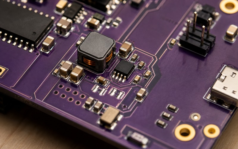
Start With the Support Load
The rail name should explain the load instead of hiding it behind a generic auxiliary label. A 5V-to-3.3V rail for a camera connector has different risk from a 12V-to-5V rail for an interface board, even if the regulator current rating looks similar. Record the nominal input, worst input high and low, output setpoint, load range, peak pulse, permitted ripple, sleep current expectation, start-up timing and fault behavior.
Small rails often get copied from a reference schematic. That can work during the first prototype, but it leaves weak ownership later. The component approval should say which load current was measured, where the ripple was measured, which capacitor set was fitted and which layout corner was used for thermal review. Without that record, a future buyer or engineer may see only a 3A buck and miss the physical limits of the board.
The support load can also be a noise source. A camera module, radio, display or motor-control helper can pull short current pulses. Those pulses may couple into the main processor, sensor reference, analog front end or cable shield. The local buck selection needs to cover load behavior, placement and return path, not a DC current number alone.
Read MP2315 as a Compact Synchronous Buck Cell
MP2315 integrates the switching power stage needed for a small synchronous step-down converter. That is useful when the board has little area for a discrete power path. The TSOT23-8 package can fit near the support load, and the external inductor and capacitors define the working power cell around it. The part is not a drop-in answer by itself; the inductor value, saturation current, capacitor derating, feedback network and copper area decide the real circuit.
The 24V rating gives margin for many intermediate rails, but the allowed input range still has to be checked against surge, adapter tolerance, automotive-style pre-regulation, motor noise or cable events if those apply. A small support buck should not be placed directly on a noisy external rail without protection review. If the rail leaves the board or sits near a connector, the ESD and transient path should be considered before the regulator approval is signed.
The 500kHz switching frequency has practical consequences. It helps keep the inductor and capacitors compact, yet the switching node and current loop still need a short, controlled layout. If a sensitive sensor, radio trace, crystal or ADC reference is nearby, place the switching area so the field and return current do not cut across that signal area.
Check Existing Design Status Before New Layout
The public MPS status is part of the sourcing review. When a manufacturer marks a device as not recommended for new designs and points to a newer option, the project should not treat the old part as a casual first choice. Existing products may keep the approved regulator if lifecycle, supply route and test evidence are acceptable. New layouts should evaluate the recommended alternative early enough to avoid a late PCB rework.
This status does not mean every existing MP2315 board has to be changed at once. It means the file should contain a clear decision. If the design stays with MP2315, note why the risk is acceptable, which exact orderable suffix is approved, what last-time or lifecycle monitoring applies, and which substitute path is allowed. If the design moves to MP2393 or another family, treat it as an engineering change with layout, compensation, thermal and qualification checks.
A compact buck part can be hard to replace even when pin count and package class look close. Enable threshold, frequency, current limit, soft start, feedback reference, compensation needs, thermal pad behavior and recommended inductor range may change. The approved alternate list should be built from tested behavior, not from a package search alone.
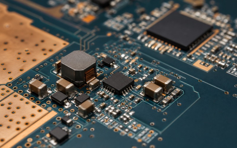
Inductor and Capacitors Decide the Real Footprint
The inductor is the visible anchor of the MP2315 power cell. Its current rating, saturation behavior, DCR, height, shielding and temperature rise need to match the real load. A small inductor can make the rail look tidy while running hot or saturating during a pulse. A larger part may improve margin but collide with enclosure height or neighboring mechanical parts. Approve the inductor by measured current and thermal result, not by nominal inductance alone.
Input capacitors should sit tight to the regulator current loop. They see pulsed current from the switching stage, and their effective capacitance falls with bias and package choice. Output capacitors shape load response and ripple at the support circuit. If the board uses MLCCs, check effective value at voltage, temperature and tolerance. If a replacement capacitor series is used later, the rail should be checked for ripple and stability again.
The bill of materials should name the inductor and capacitor families with enough detail for purchasing. A generic value is not enough for a small buck. Package, voltage rating, saturation current, temperature grade and approved alternates should be tied to the released layout and measured rail behavior.
Prototype boards should keep enough measurement access to prove that decision. Add a clean ground point, an output rail point at the regulator, and a second point near the support load. If the load is on a connector or mezzanine board, measure both sides of the path. This separates regulator behavior from trace drop, connector resistance and return current. The same test points help later when an inductor, capacitor, regulator suffix or assembly site changes.
Layout Controls Heat, Ripple and EMI
On a compact buck, layout is part of the component. The input loop should be short, the switching node should be compact, the feedback trace should avoid noisy copper, and the output path should run cleanly to the support load. Copper pour and vias help with heat, but they should not spread switching noise into a quiet signal area.
Ground strategy matters. The high-current loop, output capacitor return, feedback divider return and load return should be placed so ripple current has a controlled path. A single thin neck between the regulator and load can create voltage movement that looks like regulator error. A shared return with a sensor or reference can make a good regulator appear noisy.
Thermal review should use the actual input voltage, output voltage, load duty cycle and enclosure. A 3A rating does not guarantee a 3A continuous support rail on a small board. Loss depends on conversion ratio, switching behavior, inductor DCR, copper area and airflow. Check the hottest operating corner and nearby heat-sensitive parts.
Enable, Start-Up and Light-Load Behavior Matter
Support rails often sequence around larger systems. A camera or radio rail may need to rise after a processor rail. A peripheral rail may need to stay off during sleep. A helper logic rail may need to be present before a sensor bus is read. The enable threshold, start-up time and load behavior should be checked in the real system sequence.
Light-load behavior can matter in battery products and always-on devices. If the support load spends long periods asleep, input current, pulse mode behavior and output ripple at light load need review. Some loads care more about quiet sleep than peak current. The regulator choice should match the operating profile rather than the active load point alone.
Fault behavior should be documented. If the rail current-limits or shuts down thermally, the host firmware should not treat connected sensor or interface readings as valid. The system should know when the support rail is enabled, settled and inside tolerance before using the data or enabling the external function.
Substitution Review for an MP2315 Rail
A safe substitute review starts with the existing circuit. Record input range, output setting, inductor, capacitors, load current, switching frequency target, enable logic, thermal result, ripple result, layout constraints and lifecycle status. Then compare candidate parts against that list. A newer recommended family may need a changed inductor, capacitor set or layout pattern, even if it serves the same voltage rail.
Do not hide the manufacturer status from purchasing. If MP2315 remains approved for a service product or an unchanged legacy build, say so directly in the sourcing note. If new designs should use the replacement direction, record that boundary as well. This prevents emergency substitutions that bypass engineering review.
For production, keep one approved main option and one tested alternate path. The alternate should include the exact part, inductor and capacitor set, thermal data, ripple data and layout notes. If no alternate has been tested, the public status should trigger a risk note rather than a silent assumption that the old rail can be sourced indefinitely.
The purchasing file should carry the same boundary in plain language. State which suffix may be bought, which substitute requires engineering approval, which inductor and capacitor families are tied to the release, and which measurement must be repeated after any sourcing change. That keeps a small rail from becoming an untracked field change.
Final MP2315 Selection Checklist
Before releasing an MP2315-based support rail, confirm the exact orderable suffix, manufacturer status, replacement direction, input voltage range, output voltage, load current, pulse load, switching frequency context, inductor saturation and temperature, input capacitor placement, output capacitor effective value, feedback routing, enable sequence, light-load behavior, thermal result, ripple measurement point, EMI-sensitive neighbors, protection path and approved alternate boundary.
The part can be a practical fit for maintaining a compact auxiliary buck rail when the board already proves its electrical, thermal and sourcing conditions. For a new design, the recommended replacement path should be evaluated before layout. In both cases, approve the rail as a complete power cell around the regulator, inductor, capacitors, copper and support load, not as a single catalog line.