Free Shipping Over$200

- Products
- Marking
- Alternative

TPS65131RGER Where a Board Needs a Positive and a Negative Rail
TPS65131RGER Where a Board Needs a Positive and a Negative Rail
A board needs a positive and a negative rail when the signal chain has to swing on both sides of ground, when a bias network has to create a balanced supply, or when an LCD, OLED, sensor front end, op amp stage or small analog block cannot be powered from a single positive rail. TPS65131RGER is selected for that split-rail job. TI describes TPS65131 as a converter with dual positive and negative outputs. The RGER orderable option is in the RGE 24-pin VQFN package, and the public product page lists a 2.7 V to 5.5 V input range, a positive boost output adjustable up to 15 V, a negative inverting buck-boost output adjustable down to minus 15 V, individual enable inputs, protection functions and a 4 mm by 4 mm package.
Those facts make the part attractive, but they do not make the board finished. A split rail is a supply system with two converters, two output networks, shared input stress, shared heat and often one sensitive analog load. The engineering review has to ask why both rails are needed, what voltage and current each side uses, how the two rails start and stop, how noise moves into the signal path, and how a future substitute would be qualified without breaking the bias point or the layout.
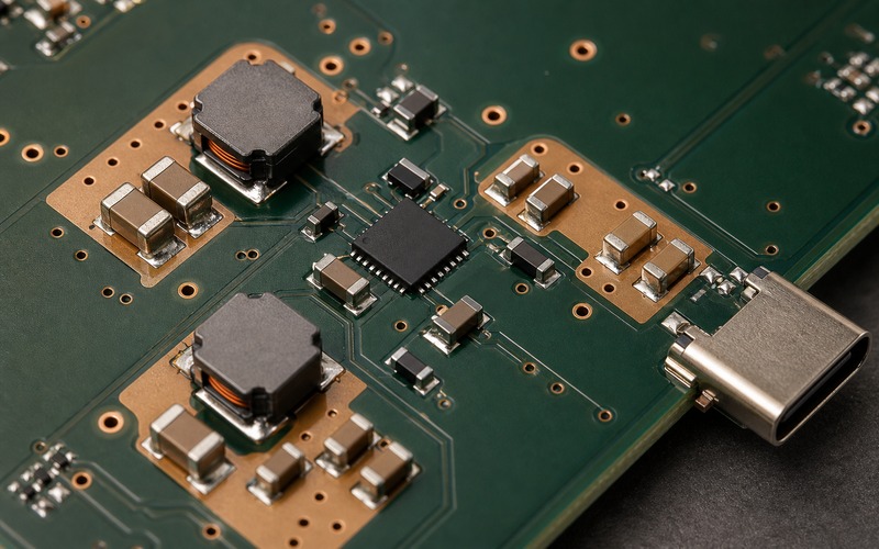
Start With the Circuit That Needs Both Rails
The selection should begin at the load, not at the converter table. A dual-supply op amp, a sensor bridge, an LCD bias circuit or an analog output stage can ask for different rail accuracy, current and noise behavior. A symmetrical plus and minus voltage may be needed in one design. A different positive and negative voltage may be needed in another. TPS65131 supports independent positive and negative outputs, so the board team should document each rail rather than describe the part as a generic dual output supply.
The load current range also deserves evidence. TI notes that output current depends on the input to output voltage ratio and current limit option. A board that asks for a high positive voltage, a high magnitude negative voltage and a low input voltage will have a different margin than a board that creates small analog bias rails from a 5 V source. Write down normal load, peak load, temperature condition and start-up load for each rail before approving the suffix.
The circuit role decides the acceptance test. A display bias rail may be judged by ripple, settling and image artifacts. An analog front end may be judged by offset, noise floor and recovery after wake-up. An op amp supply may be judged by swing, headroom and step response. The converter is approved only when the powered circuit behaves correctly, not when the two output nodes reach target voltage on an empty board.
Check the Input Source Before the Outputs
TPS65131 works from a low-voltage input range that fits battery powered and fixed 3.3 V or 5 V systems. That range is useful in portable and compact products, but it also creates real input-side stress. The positive boost stage and the negative inverting stage both pull energy through the same source. If the source is a coin cell, lithium cell, USB rail, upstream buck, small LDO or long harness, its impedance becomes part of the split-rail design.
Input capacitors should sit where the switching current enters the converter. Their voltage rating, effective capacitance, ripple-current stress, temperature behavior and ground path should be checked with both outputs operating. A weak input path can look like poor output regulation because the converter is trying to recover from a source that is sagging at the same time.
Start-up is another input-side event. If both outputs are enabled at the same moment, the input source must support two charging networks and any load that is already connected. Individual enable pins give the designer a way to sequence the rails. The right sequence depends on the load circuit, allowed bias states and firmware behavior. That sequence should be measured, not left as a schematic assumption.
Keep the Positive and Negative Outputs Separate in Review
The positive output is a boost converter path. The negative output is an inverting buck-boost path. They sit inside one device, but they do not have identical current flow, diode stress, capacitor stress, noise signature or efficiency behavior. A balanced output voltage in the schematic can hide an unbalanced layout problem on the board. Each rail needs its own voltage margin, current margin, capacitor set and probe point.
The positive rail should be checked for output voltage, load step, overvoltage protection margin, inductor current and output capacitor bias. The negative rail should be checked for absolute voltage, output ripple, diode and capacitor polarity, inverting loop area and return current path. A single test report that records only plus and minus voltage at idle is too thin for production approval.
Rail tracking matters when the load can be damaged or biased into an unwanted state by one rail arriving first. Some circuits tolerate the positive rail before the negative rail. Others need a controlled relationship. The enable pins and power-good interpretation should match the real load, and the board should be observed at turn-on, turn-off, brownout and restart.
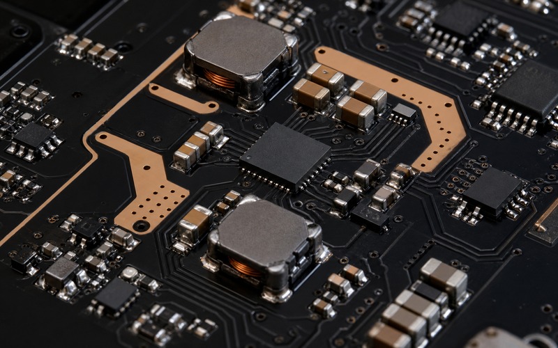
Use Layout to Reduce Noise Before Adding Filtering
A split-rail converter often sits near sensitive analog circuits because its job is to power them. That proximity is helpful for voltage drop, yet risky for switch-node noise. The first noise control step is physical placement. Keep the high di/dt loops tight. Keep switch nodes compact. Place input capacitors close to the IC. Place positive and negative output capacitors close to their respective current paths. Keep the analog sense and signal routing away from the noisy copper.
The 4 mm by 4 mm VQFN package helps density, but it also asks for careful thermal pad, via and ground-plane design. The package can sit close to the load, but the board should not crowd the current loops into a decorative pattern. Copper should serve current return, heat spreading and low impedance. If a board edge connector, FPC, sensor opening or shield can forces a poor loop shape, the converter placement should be moved before the bill of materials is frozen.
Filtering can help after the main loop geometry is sound. Ferrite beads, RC filters or post regulators may be needed for a precision analog rail. Those additions should be treated as part of the powered circuit, with stability and transient tests. A filter that lowers ripple in one condition can create load-step droop or start-up delay in another condition.
Choose Inductors, Diodes and Capacitors as a Matched Set
The switching frequency and topology let the solution stay compact, but the external parts still carry the design. Inductors should be checked for value, saturation current, DCR, core loss, temperature rise, height and magnetic field location. Diodes should be checked for voltage, current, reverse recovery, thermal path and package availability. Capacitors should be checked by effective capacitance, voltage bias, dielectric, ripple, polarity where relevant and mechanical stress.
Do not approve the support network from reference values alone. The data sheet and evaluation material give a starting point. The board voltage targets, load currents, ambient temperature, PCB copper and nearby sensitive circuits decide the approved list. If a sourcing team needs an alternate inductor, diode or capacitor, the alternate should be tested in the same output configuration, not judged only by package size and catalog rating.
For the negative rail, polarity and layout need extra care. A wrong capacitor orientation, poor return path or long inverting loop can create failures that do not appear on the positive rail. The assembly drawing, polarity marking, inspection rule and test point naming should make the negative rail hard to misbuild.
Thermal Margin Comes From Both Converters
Heat is shared through the package, copper and nearby parts. The positive and negative converters may carry different loads, but their losses meet in one small region. Efficiency values in public data help frame the review, while the board still has to prove temperature rise with the real voltage pair and load pair. A light positive rail and heavy negative rail will heat the area differently than a balanced pair.
Thermal testing should be done after the board reaches operating temperature and with the enclosure, shielding and airflow state that the product will use. A small split-rail converter can be placed near a display connector or analog section, but that can also put heat near parts whose drift matters. The test should measure converter package temperature, inductor temperature, diode temperature and the powered circuit behavior.
If shutdown, undervoltage or overvoltage protection is triggered during a fault, the system response should be known. A protection feature is useful only when the product enters a controlled state. Firmware, reset logic and user-visible behavior should be checked for short input dips, overloaded outputs and restart after a rail fault.
Package and Suffix Control the Orderable Part
TPS65131RGER is a specific orderable identity, not a broad description. The RGE package is a 24-pin VQFN option, and the land pattern, thermal pad, stencil design and inspection method belong in the release data. A purchasing note that says TPS65131 without suffix detail can create uncertainty when reels, package options or alternates are reviewed.
Small QFN packages also need production discipline. Check solder voiding, wetting, placement accuracy and X-ray access if the process requires it. Add test pads for input, both outputs, ground, enable pins and any load-side sense point. If the board is too dense for test access, fault analysis will be slow when a rail comes up wrong.
Documentation should connect the electrical approval to the orderable item. Record voltage targets, resistor values, inductor part numbers, diode part numbers, capacitor stack, enable sequence, probe points, thermal result and allowed substitutes. That record prevents a future layout spin from copying the symbol while losing the proof.
Substitution Risk Is Higher on a Split Rail
A split-rail substitute cannot be approved by input range and package alone. Another part may offer similar positive and negative outputs but use different compensation limits, current limits, switching frequency, enable logic, protection behavior, package pinout or external network. The load may also depend on rail sequence and ripple behavior. Treat a substitute as a tested board variant until the evidence matches.
The approved alternate list should include exact orderable parts, package constraints, support component changes, sequencing notes and test results. If no alternate has been verified, say so in the internal purchasing record and leave the public article focused on selection method. Buyers and engineers need a clean boundary between a stocked similar part and a qualified replacement.
For long-life products, second-source planning should be done early enough to test the alternate on hardware. Waiting until the approved converter is constrained often forces hurried layout and support-part changes. A split rail powers sensitive circuits, so an untested change can create offset, noise, display artifacts or wake-up faults that are harder to trace than a missing voltage.
Final TPS65131RGER Selection Checklist
Before approving TPS65131RGER, confirm the exact suffix, RGE package, input source range, positive voltage, negative voltage, load current for each rail, current limit option, enable sequence, input capacitor bank, inductor set, diode set, output capacitor stack, feedback resistor values, output ripple, load-step result, start-up behavior, thermal rise, protection response, test point access and approved alternate boundary.
The part is a strong candidate when a compact board needs both a positive and a negative rail from a low-voltage source, and the engineering record proves that both rails behave correctly on the real PCB. It is a weak candidate when the design has no measured load profile, no rail sequence rule, no thermal evidence or no plan for support-part substitutions. Approve the converter as a split-rail supply system, then verify the powered circuit rather than the empty voltage nodes.