Free Shipping Over$200

- Products
- Marking
- Alternative

TPS546B24A in Multiphase Power for a High Current Core
TPS546B24A in Multiphase Power for a High Current Core
TPS546B24A enters the AI board review at the point where one buck converter is no longer a clean answer. A high current core rail can pull fast load steps, sit beside a hot processor or accelerator, and demand a voltage target that leaves little room for copper loss, sensing error or phase imbalance. TI describes TPS546B24A as a 2.95 V to 18 V, stackable 20 A synchronous buck converter with pin-strapping and PMBus. The same public product material states that two, three or four devices can be stacked with current sharing up to 80 A for a single output. That makes the part less like a generic regulator choice and more like a rail architecture choice.
The approval question is not whether the data sheet has a high current line. The question is whether the board can divide that current into phases, keep each phase electrically similar, sense the load accurately and move heat away from each regulator without hiding a fault. TPS546B24A can help when an AI accelerator, FPGA, ASIC, network processor or dense CPU rail needs more current than one compact converter should carry alone. It also adds a control and verification burden. The designer has to prove phase spacing, compensation, telemetry, sequencing and thermal sharing on the real board.
Start with the Core Rail, Not the Converter
A high current core rail is set by the load before the regulator is chosen. The rail voltage, allowable droop, peak current, load-step edge rate, power-up sequence, power-down behavior and remote-sense target come from the processor or accelerator. If those limits are vague, a multiphase converter can look better on paper than it behaves in hardware. Each phase may be capable, but the rail will still fail if the load asks for a faster transient than the output network and control loop can support.
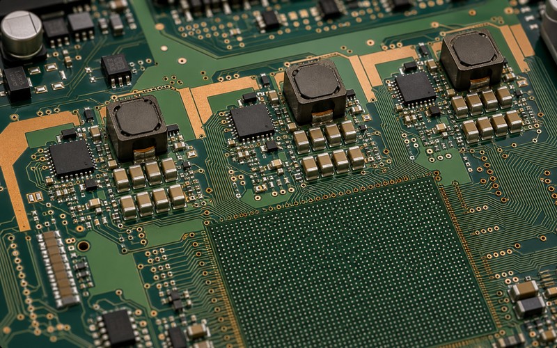
The first review should draw the rail from the load pins backward. Mark the BGA power balls, the local decoupling field, the bulk capacitance, the copper necks, the remote-sense pickoff, the regulator phase locations and the input-current entry. Then decide whether TPS546B24A phases can sit where the rail needs them. A phase placed far away can pass schematic review and still lose the point of a multiphase rail because current reaches the load through narrow copper or a long shared path.
For AI boards, the hard moment is often a workload transition: idle to inference burst, memory access to tensor operation, or a clock domain waking at the same time as another rail. The part choice should be checked against that waveform, not against a steady load number. If the workload is not final, leave margin in the phase count, capacitor bank and copper path rather than approving a rail that only fits the first firmware build.
Use Stacking as a Current-Sharing Problem
TI positions TPS546B24A as stackable, with current sharing across two, three or four devices. That feature is useful because the designer can build a higher current rail from repeated regulator phases instead of asking one package to carry the full load. It also means the board must let the devices behave like matched phases. Uneven input impedance, unequal inductor heating, different output copper length or poor sense routing can make a shared rail run as if one phase is doing more work than the rest.
Place the phases with symmetry in mind, but do not confuse visual symmetry with electrical symmetry. A neat row of regulators may look balanced while one phase has a shorter input path, one phase sits near a hot accelerator corner and one phase has a different route to the output capacitor bank. Review the copper and via field for each phase as a current path. The inductor, high-side and low-side switching nodes, input capacitors, output capacitors and ground returns all need comparable treatment.
The phase plan should also define what happens when the product variant changes. A board may begin with two devices for a lower current SKU and move to three or four for a higher current SKU. That plan needs footprints, optional passives, firmware configuration, test coverage and thermal proof. Do not leave the higher phase count as a future note. It has to be a built board option or a new design.
Pin-Strapping and PMBus Are Design Boundaries
TPS546B24A can be configured through pin-strapping and PMBus. That is helpful in production because default behavior can be set with hardware while firmware still has access to telemetry and commands. It also creates two sources of truth. The resistor settings, PMBus defaults, firmware writes and production test script must agree on output voltage, ramp behavior, address, fault response and margining.
A clean release package should list the hardware strap values beside the firmware assumptions. If the board management controller writes a voltage, a margin value or a fault limit after boot, the design should still be safe before that write occurs. If the product can boot in a field condition with firmware absent or delayed, the strap defaults matter. If the firmware changes later, the power rail should have a regression test that checks the converter configuration rather than relying on a software review.
PMBus telemetry can make the rail easier to supervise. TI documentation calls out telemetry for output voltage, output current and internal die temperature. Treat those readings as engineering signals that need calibration context. They can help find imbalance and overheating, but they do not replace probing at the load, checking current through each phase or measuring thermal rise on the final assembly.
Remote Sense Must Read the Load, Not a Convenient Plane
A high current core rail can lose meaningful voltage in copper, vias and package paths. TPS546B24A documentation describes differential remote sensing and output-voltage accuracy across a wide junction-temperature range. The benefit depends on where the sense lines land. If they pick up voltage at a regulator-side capacitor bank, the converter may regulate the wrong point while the BGA load sees a lower rail during a burst.
Route sense traces as a quiet measurement pair, not as ordinary routing that happens to reach the load. Keep them away from switching nodes, inductor copper and pulsed returns. Pick the sensing point that represents the load rail after the main copper drop, and guard the route from noise that could make the loop chase a false signal. If the package or processor vendor specifies sense-pin guidance, align that with the regulator guidance before layout is released.
Remote sense also changes fault analysis. A broken sense connection, swapped sense polarity, noisy route or poor test access can make the rail behave in confusing ways. Add planned measurement points for the regulator output, the load-side rail and the sense pair. Those points save hours during first power-up and give manufacturing a way to separate a regulator issue from a board-level drop.
Inductor and Capacitor Choices Set the Real Transient
TPS546B24A is a regulator IC, not a complete power module. The external inductor, input capacitors, output capacitors and layout still set much of the rail behavior. A multiphase rail can reduce ripple and spread heat, but it can still sag if the inductors saturate, if output capacitance falls under DC bias, or if the capacitor field sits far from the load.
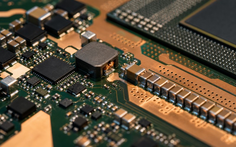
Choose the inductor for current rating, saturation behavior, DCR, size, thermal rise and loss at the selected switching condition. The inductor should be checked at the expected phase current and at overload or transient conditions, rather than by a catalog current line alone. Since several inductors sit near each other, their heat adds. A part that is fine as a single phase may run hotter when three phases sit beside a hot core.
Capacitors need the same physical review. The input side has to absorb pulsed current without making the upstream rail noisy. The output side has to support load steps at the BGA pins. Mix ceramic and bulk capacitance with bias, aging, temperature and ripple current in mind. A dense MLCC bank may look large in schematic capacitance and become smaller in circuit. The rail should be measured at room temperature and after thermal soak.
Thermal Balance Is as Important as Current Balance
Stacking devices spreads current, but it does not automatically spread heat. One phase may sit near airflow, one may sit under a shield, one may share copper with a hot processor edge, and one may lose heat into a thinner plane section. If thermal paths differ, current sharing can look acceptable at light load and drift at high load or after a long inference run.
Thermal review should include each regulator package, each inductor, the input capacitor bank, the output capacitor bank and the copper between the phase and the load. Capture thermal images during the real workload. Record ambient condition, airflow state, board orientation, input voltage and output current. A rail that passes on an open bench can fail inside a sealed edge box or in a telecom chassis with a different airflow pattern.
The layout should give each phase enough copper and vias to move heat. That does not mean flooding copper without thought. The switch node needs controlled copper, the power path needs low impedance, the exposed pad needs thermal vias, and sensitive routing needs distance from noise. Thermal and electrical layout cannot be separated on this rail.
Protection Behavior Needs Board Evidence
A high current core rail should be tested beyond normal operation. Start-up into the final load, shutdown, margining, load release, short-circuit behavior, overtemperature response and fault reporting all need evidence. If several TPS546B24A devices are stacked, the test should observe how the phases respond together. A fault in one phase should not leave the system in a half-powered state that damages the processor or confuses sequencing.
PMBus fault logs can help, but the oscilloscope still matters. Probe the input rail, output rail, enable, power-good, selected telemetry lines and the load-side sense point. Watch the rail at fast and slow time scales. Some problems show as a single dip during a load edge, while others show as heating, drift or periodic control interaction.
Manufacturing test also needs a practical version of this review. The factory may not run the full accelerator workload, but it can check strap values, address response, output voltage, telemetry sanity, current share at a known load and thermal rise during a short stress step. If a board has optional phase population, the test must know which phase count is expected.
Substitution Risk Is Higher in a Multiphase Rail
A single buck converter can be difficult to replace. A stackable PMBus rail raises the bar because the substitute has to match electrical behavior, configuration, telemetry, current sharing, package, thermal path and firmware assumptions. Even a pin-compatible or category-matched device can force a new control review.
The approved list should separate exact TPS546B24A orderable variants from possible alternates. An alternate should stay unapproved until it has passed load-step testing, thermal testing, fault testing, PMBus behavior checks and assembly review. If a buyer is asked to source a replacement, the request should include the exact rail role, current target, package, controller and firmware constraints.
For a long-life product, keep the rail evidence with the bill of materials. Store the phase count, inductor choice, capacitor list, strap values, PMBus settings, remote-sense points, thermal images, load-step plots and known forbidden swaps. That record keeps a future change request from treating a power rail as a line-item price comparison.
Final TPS546B24A Selection Checklist
Before TPS546B24A is approved, confirm the exact orderable part, input range, target rail voltage, phase count, maximum and transient current, selected switching condition, inductor current and thermal margin, input capacitor network, output capacitor network, PMBus address plan, strap values, firmware writes, remote-sense landing point, power-good and fault response, measurement points, thermal path, assembly limits and accepted alternates.
The part is a good candidate when the product needs a compact high current core rail with digital supervision and a clear multiphase path. It is a weak fit when the board cannot place phases evenly, cannot route remote sense cleanly, cannot validate firmware-controlled settings or needs casual second sourcing. Treat the rail as a power architecture, then test it at the load pins after the board is warm and the real workload is running.