Free Shipping Over$200

- Products
- Marking
- Alternative

TDM22545DXUMA1 as a Dense Power Stage with the Inductor Inside
TDM22545DXUMA1 as a Dense Power Stage with the Inductor Inside
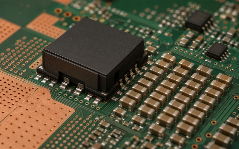
TDM22545DXUMA1 belongs in the AI board power review because it moves two hard pieces of the high-current rail into one dense package: the smart power stages and the inductors. Infineon positions TDM22545D as a dual-phase 140 A OptiMOS power module, and the public data sheet lists two smart power stages, two inductors, integrated decoupling and a compact 10 x 9 x 5 mm LG-MLGA-72 package. That combination changes the board problem. The engineer is no longer placing separate MOSFETs and large external inductors around the rail; the review moves toward controller matching, capacitor placement, heat spreading, land pattern control and proof that the package can sit close to the accelerator without creating a new thermal or assembly problem.
The part should not be approved as a shortcut around power design. It compresses the hot switching loop, reduces some layout degrees of freedom and can help a dense rail fit near an AI accelerator, FPGA, CPU or datacenter device. It also concentrates current, heat, solder joints, telemetry pins and qualification risk into a single orderable item. The selection question is not whether the module has a large current number. The question is whether the product can use that density without losing repair margin, thermal margin, controller freedom or second-source options.
Read the Module as a System Part
A discrete buck stage lets the team choose MOSFETs, driver, inductor, current sense method, bootstrap parts and compensation support as separate choices. TDM22545DXUMA1 folds a large part of that switching stage into a module. Infineon documentation describes a dual-phase power module with integrated inductors, internal decoupling and reporting features for current and temperature. That level of integration is useful only if the surrounding system is reviewed as a module system.
The controller still matters. PWM behavior, phase count, current balancing, fault handling, reporting pins, power-good handling and sequencing have to match the module. If a controller was selected around a different power stage family, the design should not assume the same compensation, telemetry interpretation or protection timing will carry across. Read the module data sheet beside the controller data sheet and the accelerator rail requirements.
The module is also a mechanical part. Its package size, height, solder land, keepout and heat path affect the board stack and enclosure. A dense module can free space around the rail, but it may need stronger copper spreading, cleaner airflow or more careful reflow control than a looser discrete design. Those tradeoffs belong in the same approval note as the electrical data.
The Integrated Inductor Changes Layout Risk
The visible absence of a large external inductor is the point. When the inductor sits inside the package, the designer loses the chance to move it a few millimeters, rotate it around a connector, change its DCR or choose a taller magnetic body late in layout. In return, the high-current switch node and magnetic element are controlled by the module vendor, and the board team can keep the power stage compact.
This is a good fit when the product is short of area and the rail current is high enough that a discrete stage becomes hard to fit cleanly. It is a weak fit if the board needs a custom inductor value, a special height limit, a different thermal spread, or a supply plan that depends on easy substitutions. The inductor is no longer a flexible line item on the bill of materials. It is part of the power module identity.
Layout review should focus on what still sits outside the package: input capacitors, output capacitors, controller routes, enable and reporting lines, bootstrap or support parts called for by the data sheet, and copper return paths. The package handles part of the loop, but the board still creates the input and output impedance the accelerator will see.
Place Capacitors Around the Package, Not Around a Schematic Symbol
Infineon lists integrated decoupling inside the module, but that does not remove the need for product-specific input and output capacitors. The internal capacitors help the package behave as intended. The board capacitors still decide input ripple, rail droop, local energy delivery and stability with the controller and load. Treat the recommended external network as a physical layout, not as a line in a schematic.
Input capacitors should sit where the current pulse enters the module. Output capacitors should sit where the load can use them, with low-inductance paths to the accelerator rail and ground. Large ceramic banks may be needed near the module and near the load, depending on the board stack and transient target. Effective capacitance should be checked at operating voltage and temperature, since MLCC capacitance can fall under DC bias.
The two phases also need symmetry. If one side of the module sees a cleaner input path or a shorter output path, the rail can pick up imbalance and heating. The package may integrate the phases, but the board copper still decides how evenly current spreads into planes and capacitor arrays. The module land pattern, via placement and copper pours should be reviewed with current flow in mind, rather than manufacturability alone.
Thermal Review Is Part of Electrical Approval
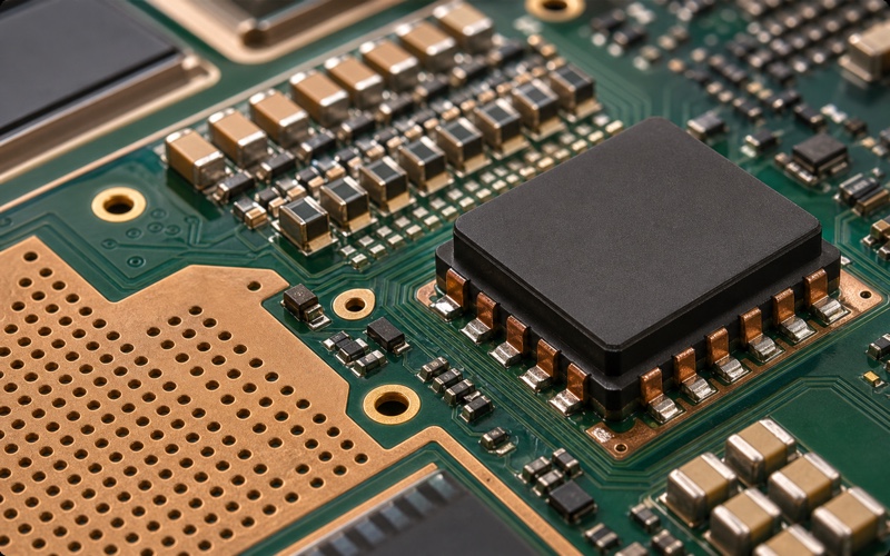
High current in a compact package turns thermal design into electrical design. Temperature affects MOSFET resistance, current sharing, protection thresholds and long-term reliability. The public product material positions TDM22545D for high-current rails in systems such as AI accelerators, CPUs, FPGAs and telecom or datacenter equipment. Those systems often place the power stage near a hot load, which means the module and accelerator can heat each other.
Do not approve the module from room-temperature waveforms alone. Measure rail response after workload heat soak, with the real copper stack, heat spreader, airflow or enclosure installed. The power module needs enough copper and vias to move heat away from the package. The accelerator nearby needs its own thermal path. If the two paths fight for the same copper or air, the rail margin can shrink during the exact workload that raises current.
The package height and top-side clearance matter too. A heat spreader, lid, shield can, airflow duct or neighboring connector may change the local temperature. The module may be compact on the XY plane and still difficult in the Z direction if the mechanical stack was planned for flatter discrete parts.
Check the Controller and Telemetry Boundary
A power module with reporting features gives the system more visibility, but visibility has to be interpreted correctly. Current reporting, temperature reporting, fault outputs and enable behavior should be mapped to the controller and firmware. If the board management controller uses those signals to throttle the accelerator, reset the rail or log a fault, the thresholds and timing need bench evidence.
Current sharing across phases also belongs to the controller boundary. A dual-phase module can reduce routing complexity, but the rail is still a multiphase system. The control loop, compensation, PWM timing and load-step behavior should be checked with the actual controller and capacitor network. A stable demo board does not prove a different board stack, capacitor mix and airflow will behave the same.
Telemetry traces are small, but they run near a noisy power block. Route them away from switch-node copper and high-current returns. If the layout puts reporting traces next to the wrong copper, the firmware may see noise as behavior. The physical routing and the software filtering should be reviewed together.
Assembly and Inspection Need Their Own Gate
The compact package makes the rail smaller, but it also puts many solder joints under and around one power part. Land pattern, stencil design, solder voiding, coplanarity, reflow profile and X-ray inspection become part of part approval. A dense power module that performs well on a clean evaluation board can still fail if the production process leaves voids, bridges or weak wetting under the high-current pads.
Inspection access matters. If a discrete inductor overheats, the engineer can often see the part, probe around it or swap it. With an integrated module, debug leans harder on thermal imaging, electrical probing at planned test points and assembly inspection. Add rail probe points, input probe points, ground references and any reporting-signal access before the board is released.
The procurement team also needs the exact package and suffix. TDM22545DXUMA1 is an orderable identity, not a generic power module description. If a drawing, ERP item or alternate list drops part of the suffix, the board can receive a part that does not match the approved assembly or product documentation.
Document the board-side evidence as part of the released package. Keep the stencil aperture rule, X-ray acceptance rule, thermal-camera reference image, load-step waveform, controller setting, capacitor list and measurement point in one review file. That record helps a manufacturing engineer separate a solder issue from a design issue, and it helps a buyer understand why a visually similar module cannot be substituted without a new test run.
The first production build should be treated as an electrical and assembly correlation run. Compare the module temperature, rail droop, input ripple, fault signal behavior and inspection result against the prototype data. If the production PCB stack, copper weight or solder finish changed after prototype approval, repeat the high-current tests instead of carrying the old waveform forward.
Substitution Is a Board Variant, Not a Casual Swap
Integrated power modules are hard to second-source by package outline alone. The internal inductor value, current path, reporting behavior, thermal design, pinout and recommended external network can differ between parts that look similar in a category search. A substitute may force a different controller setting, different capacitors, different land pattern or different thermal solution.
For a long-life AI product, treat any substitute as a board variant until proven. The approval plan should include transient response, efficiency in the real load range, thermal rise, current reporting, fault behavior, start-up, shutdown, reflow inspection and mechanical clearance. If the alternate needs different passives or controller settings, name those changes in the approved list.
That discipline protects purchasing as well as engineering. During a shortage, a vague phrase such as dual-phase power module with internal inductor is not enough. Buyers need the exact approved part, approved alternates, package constraints, controller pairing and any forbidden substitutions.
Final TDM22545DXUMA1 Selection Checklist
Before approving TDM22545DXUMA1, confirm the exact OPN and package, input voltage range, target rail voltage, current profile, controller compatibility, PWM and phase behavior, external input and output capacitor set, thermal copper and via design, module keepout, height clearance, assembly inspection method, telemetry routing, fault behavior, load-step result, warm-board waveform and alternate-part boundary.
The part is a strong candidate when density is a real board constraint and the product can use an integrated inductor module without hiding thermal, assembly or sourcing risk. It is a poor fit when the design still needs late inductor tuning, loose controller freedom or easy second sourcing. Treat the module as a complete power-stage decision, then prove the rail at the load pins under the workload that the accelerator will run.