Free Shipping Over$200

- Products
- Marking
- Alternative

Holding the Rail Steady Under a Sudden Accelerator Load
Holding the Rail Steady Under a Sudden Accelerator Load
An accelerator rail can look correct until the model wakes up. The bench supply is stable, the board idles cleanly, the regulator data sheet current rating seems generous, and then a convolution burst or transformer block pulls charge faster than the power path can answer. The result is not a graceful current increase. It is a short droop at the die, sometimes followed by overshoot, recovery ringing, reset behavior, timing errors or an inference result that changes only when the board is warm. Holding the rail steady starts by treating the load step as the main design event, not as a late oscilloscope check.
The topic is broader than choosing a larger regulator. A sudden accelerator load is seen through the regulator loop, the inductor, the output capacitor bank, the ceramic capacitor bias loss, the plane impedance, the package inductance, the sense point, the input path and the sequencing state around the load. A part can meet its steady current number and still fail the rail when the edge current arrives. The selection review has to follow the charge path from the input connector to the silicon pins and back through ground.
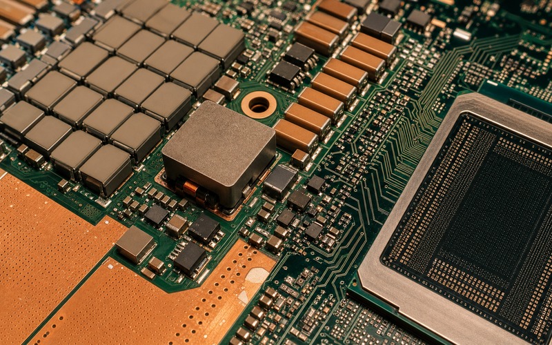
Define the Load Step Before Selecting the Regulator
The useful starting point is the load waveform the accelerator will create. Average current gives the thermal story, but transient current gives the rail story. A vision accelerator may move from a low activity state into a frame-processing burst. A voice device may wake its compute block after a trigger. A gateway may start a model while radio traffic, memory access and sensor capture are already active. Each case creates a different load edge, duration and repetition pattern.
Engineers often begin with a power budget table because it is easy to fill. That table should be joined by a transient table: idle load, step load, step rate, allowed droop, allowed overshoot, recovery window, start-up state and rails that switch at the same moment. If the silicon vendor gives a transient target, use it. If the target is missing, measure a development board or run a conservative bench profile rather than approving parts from average power alone.
The rail name also matters. A core rail with a narrow tolerance and high current asks for another review than an I/O rail or an analog sensor rail. A memory rail may care about noise during bursts. A PLL rail may need isolation from digital current. The regulator choice, output network and layout are all tied to the rail role.
Separate Current Rating from Transient Response
A buck converter or power module current rating is not a promise that the rail will stay inside its window during a load edge. The current rating describes what the stage can supply under stated thermal and electrical conditions. Transient response describes how fast the loop and output network can move energy to the load while the feedback system reacts. Both have to pass.
A higher current regulator can still have a slow loop, a weak compensation point or an output network that rings with the board. A smaller stage can behave better if the load step is modest and the capacitor bank is placed with low inductance. The question is not which part has the largest number in the table. The question is whether the selected power path meets the droop and recovery requirement at the point where the accelerator takes current.
Review control mode, switching frequency range, compensation method, inductor value, current limit behavior and transient plots in the regulator documentation. Then check whether those plots use conditions close to the product. If the test board has a different output capacitor set, different input voltage, different load step and generous copper, the plot is a clue rather than a direct approval.
Place the First Charge Where the Load Can Reach It
The output capacitor bank supplies the first part of the load edge before the regulator loop catches up. That bank is a physical network, not a single schematic symbol. Large capacitors provide energy over longer portions of the event. Smaller ceramics help at faster edges. Package inductance, mounting pads, via placement and plane geometry decide how much of that stored charge reaches the die in time.
Ceramic capacitors also lose effective capacitance with DC bias, voltage rating, temperature and package choice. The design should use effective capacitance at operating bias, not the catalog value printed for a zero-bias test condition. The review should include capacitor voltage rating, dielectric class, package stress, mounting location, anti-crack needs and availability of approved alternates. A small MLCC change can move impedance enough to show up as droop or ringing.
Do not let the capacitor array drift away from the load because the layout is crowded. The regulator output bulk can sit near the power stage, but the load-side high-frequency bank needs short current loops to the accelerator power and ground pins. If the board uses multiple layers, the return path should be as deliberate as the supply path. A neat top-side row of capacitors can still be weak if its ground vias and planes force current through a long loop.
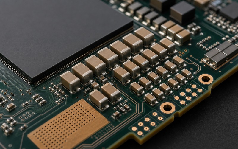
Inductor and Power Stage Choices Set the Recovery Shape
The inductor stores and releases energy, but it also limits how fast current can rise. A lower inductance value can improve current slew in some designs, while raising ripple and changing stability. A higher value can reduce ripple, but slow response. Saturation current, core loss, DCR, temperature rise and acoustic behavior all matter because the accelerator may repeat load bursts many times during a workload.
Integrated power stages and power modules reduce part count and can shorten high-current loops, yet they still need the correct output network, thermal path and remote loading check. A module with an inductor inside can be attractive near a dense compute device, but package height, thermal spreading, input capacitor placement and repairability should be reviewed with the same discipline as discrete regulators.
Current limit deserves a separate look. A rail can pass normal operation and still touch a protection threshold during cold start, batch variation or a workload with synchronized blocks. If the current limit folds back during a burst, the failure may look like a software reset. The protection setting should leave enough margin for the real load step without masking a short circuit or assembly fault.
Feedback Should Measure the Rail the Silicon Uses
Feedback taken at the wrong point can make the regulator look stable while the silicon sees a different voltage. Local feedback near the regulator senses the output stage. Remote sense or Kelvin-style routing senses the rail closer to the load, but it adds routing and noise concerns. The right choice depends on current, board size, plane drop and tolerance.
If remote sense is used, route the sense pair as a measurement path, not as a power trace. Keep it away from switch nodes, high dV/dt copper and noisy digital edges. Protect the sense pins from open-circuit assembly states if the regulator documentation requires it. If local sense is used, estimate plane drop and validate the rail at the load with a short ground spring or a proper coax probe point.
The sense target should match the acceptance test. If the production test measures at the regulator output while the failure occurs at the accelerator package, the test can miss the problem. Add probe access that can see the load-side rail, ground bounce and input droop during a programmed workload. The board does not need a lab instrument forever, but the design should allow real verification before release.
Input Path and Sequencing Can Trigger the Same Failure
A fast load step on the output rail pulls energy through the input side as well. If the input connector, fuse, cable, protection device, upstream regulator or input capacitor bank is weak, the local buck stage may lose headroom while trying to recover the output. The symptom can resemble output instability even when the output compensation is reasonable.
Input capacitors should be placed close to the switching stage and chosen for ripple current, voltage bias, surge margin and temperature. If the product is powered from USB, PoE, battery, a wall adapter or a long harness, include that source impedance in transient tests. A bench supply with short thick leads can hide a field problem.
Sequencing also changes the first load event. An accelerator rail may come up while memory rails, I/O rails, clocks or reset logic are still settling. A workload may start before the thermal and power management code is active. The enable timing, power-good thresholds, soft-start behavior and reset release point should be checked as a system. A rail that is stable after boot may still fail during the first few milliseconds after release.
Thermal Margin Changes Electrical Margin
Load bursts heat the power path. The regulator package, inductor, copper pours and nearby accelerator all share the thermal environment. As temperature rises, resistance changes, current limit behavior can shift and capacitor performance can move. A rail that passes a cold transient test may show different droop after a long workload in a closed enclosure.
Thermal review should use the actual airflow, enclosure and board stack. A power module beside a hot accelerator needs copper spreading, via arrays and clearance from heat-sensitive components. If the inductor is close to a sensor, microphone or magnetometer, its field and heat should be reviewed as well. Power integrity is electrical, but the margin is lost through heat as often as through a missing capacitor.
Measure transient response after the board reaches operating temperature. If the application has burst and idle cycles, test both single events and repeated events. If a fan, enclosure vent or heat spreader is part of the product, test with that mechanical stack installed.
Substitution Needs a Transient Bench Test
Power parts invite substitution because many regulators share current class, package outline and nominal output range. That is not enough for an accelerator rail. A substitute can differ in compensation limits, minimum on-time, switch resistance, thermal pad design, current-limit slope, power-good timing or recommended output capacitor range. Those differences can move the transient result.
The approved alternate list should carry exact orderable parts, package details, allowed inductor and capacitor sets, compensation settings, thermal assumptions and any layout notes. If a second source demands a different inductor or capacitor mix, record that as a qualified variant rather than a casual drop-in. Buyers need that boundary before a shortage turns into an untested board change.
The bench test should reproduce the product load as closely as practical. Use a real workload when possible, then add electronic load steps to cover margins the software may not reach every time. Capture load-side voltage, input voltage, switch node behavior if accessible, temperature and recovery time. Keep the plots with the part approval record so a future replacement can be compared against the same evidence.
Final Rail Stability Checklist
Before approving the power rail for an AI accelerator, confirm the load-step profile, allowed droop and overshoot, regulator control method, inductor value and saturation margin, effective output capacitance, load-side capacitor placement, remote or local sense point, input capacitor bank, source impedance, current-limit behavior, sequencing, power-good timing, thermal rise, probe access and alternate-part test.
The rail is ready when it passes the workload at the load pins, after warm-up, across the expected input range and with every approved component set. It is not ready when the evidence stops at steady current, a data sheet example board or a no-load start-up waveform. The accelerator does not draw current like a resistor, and the power design should be reviewed at the speed of the load it feeds.