Free Shipping Over$200

- Products
- Marking
- Alternative

Pairing a Blower with a Part That Throttles When Hot
Pairing a Blower with a Part That Throttles When Hot
A chip that throttles after warm soak is already asking for a different thermal path. The device may look stable during a short bench run, yet the shipped workload can hold the accelerator, memory and power rails hot long enough for clock speed to fall.
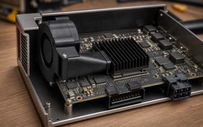
Adding a blower is not a cosmetic upgrade to a passive heatsink. It changes the thermal circuit, the electrical budget, the acoustic profile, the dust path, the failure modes and the mechanical envelope. The blower must be selected with the hot part, the heatsink, the duct, the enclosure and the control loop in the same review.
Start With the Throttle Signature
The first clue is the shape of the slowdown. A brief frequency drop after a burst points to transient heat storage. A steady decline after several minutes points to an airflow or enclosure limit. A sharp drop tied to a single rail, camera mode or radio event may come from local power heating rather than the accelerator alone.
Record the workload that triggers the event. Frame rate, model size, memory bandwidth, display output, storage writes and wireless traffic all change heat. A blower sized against a light demonstration can miss the final product state if the final software keeps several hot zones active together.
Use sensor data carefully. Junction estimates, heat-sink base temperature, local board temperature, rail current and performance logs each describe a different part of the failure. The blower decision should answer which link is limiting: chip-to-heatsink contact, heat-sink-to-air transfer, enclosure air exchange or surrounding heat sources.
The throttle threshold also sets the control target. If the product can accept a short clock reduction during rare peaks, a small blower and duty limit may be enough. If latency must stay fixed, the airflow path needs margin across ambient, orientation, dust and production tolerance.
Choose Airflow Before Blower Size
A blower is useful because it creates pressure across a restricted path. That makes it different from placing a fan near the board and hoping the air mixes. The design should name the path: intake, impeller, outlet, duct, fins, hot board area, exhaust slot and the air volume that leaves the enclosure.
Airflow without direction wastes power. If the outlet hits a solid wall, crosses the fins at the wrong angle or escapes around the heatsink, the blower may raise noise while leaving the hot part near its old limit. The fin direction, duct wall and exhaust opening should be drawn before the supplier part is chosen.
Static pressure matters when the path is narrow. Dense fins, dust screens, small inlet slots, foam seals and tight bends all add resistance. A blower with a pleasant free-air number can perform poorly once it is installed in a shallow enclosure with a small exhaust opening.
The intake deserves the same attention as the outlet. A blower pressed against a wall or cable bundle can starve even when the outlet is aimed correctly. Keep the inlet clear through assembly and service, and check that nearby flex cables or labels cannot fold into the intake area.
Place the Blower Where It Can Be Built
The best thermal location is not always the best production location. A blower needs screw bosses, clearance for its housing, a cable route, a connector, vibration control and a way to survive drop or shock. If those items are added after the layout is nearly frozen, the airflow path can become an awkward compromise.
Board-edge placement often helps because the blower can pull air from one side and push it across the heatsink toward an exhaust slot. It also keeps the intake serviceable and leaves room for a short duct. The connector and cable should face outward or toward a real harness path, not into the middle of the board where service becomes difficult.
The blower should not create a new hot spot. Its motor driver, connector, cable and nearby regulator add small losses and can block copper spreading. Keep the high-current power path, the accelerator heat path and the mechanical mounting points from fighting for the same board area.
Vibration is part of placement. A light board with a tall heatsink can amplify fan vibration into connectors, solder joints or acoustic panels. Mounting pads, screws, grommets and enclosure ribs should be selected with both airflow and vibration in mind.
Match Fins, Duct and Exhaust
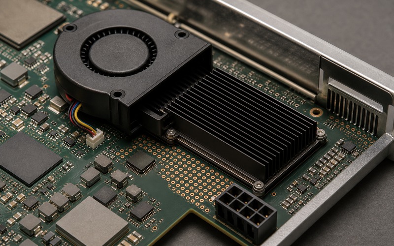
The heatsink should be chosen for forced airflow, not borrowed from the passive version without review. Fin spacing, fin height, base thickness and orientation can change when air is driven through the part. A passive sink with tall wide fins may not use the blower pressure well; a dense sink may need more pressure than the blower can provide.
A short duct can make the difference between cooling the heatsink and cooling the enclosure wall. It does not need to be complex, but it should reduce bypass air. The duct edge should meet the blower outlet and heatsink face with enough tolerance for assembly, thermal expansion and vibration.
The exhaust path must be credible. Air that warms inside the box and then circles back into the intake raises the starting temperature. The enclosure should separate inlet and outlet enough that the blower receives cooler air during continuous operation.
Do not ignore nearby components. Memory, regulators, inductors and sensors may sit in the same airflow stream. Air that leaves the heatsink can be warm, so the downstream path should avoid temperature-sensitive parts when the board has another routing option.
Dust and blockage change the answer over time. A narrow exhaust slot may look tidy in a render but lose margin as dust accumulates. If the product works in a cabinet, vehicle, outdoor box or factory panel, the air path should be judged after plausible fouling instead of relying on a clean-bench result.
Power, Noise and Control Are Part of Selection
The blower needs an electrical supply that remains stable during the same workload that heats the accelerator. Startup current, speed changes and motor commutation can disturb a sensitive rail if the blower is tied into a weak auxiliary supply. The fan rail, return path and filtering should be reviewed beside the compute rails.
Noise includes far more than sound pressure. Tonal whine, bearing quality, PWM frequency, resonance with the enclosure and airflow through slots all affect whether the product feels acceptable. A small blower running near full speed can be less pleasant than a larger part at lower speed, if the enclosure allows it.
Control policy should be explicit. Some designs run the blower whenever the accelerator is active. Others ramp speed from a board sensor, a junction estimate or a workload state. The sensor location matters: a sensor far from the hot path may react late, while a sensor near a regulator may command speed for the wrong reason.
Fail behavior belongs in the design review. If the blower stalls, cable disconnects or wears out, the product should reduce workload or shut down before the hot part crosses its safe operating boundary. A tach signal, current monitor or thermal timeout may be needed when fixed performance matters.
Measure the Installed System
Open-board fan tests are useful for learning, but they cannot release the product. The final check needs the real enclosure, cable routing, filters, gasket, orientation, mounting surface, ambient condition and software workload. A lab fan helping the intake or a missing lid can turn a failing airflow path into a false pass.
Measure enough points to see the path. Use the accelerator thermal sensor or estimate, heat-sink base, local board zone, blower inlet air, exhaust air, nearby regulator and end-of-test performance. If only the external case is measured, the design may miss an internal recirculation problem.
Run long enough for the enclosure to settle. Forced airflow can make the heatsink stabilize quickly while the box, metal bracket and surrounding air continue warming. The release test should continue until the important temperatures flatten or the product reaches a defined limit.
Check several orientations. A blower helps reduce orientation sensitivity, but inlet and exhaust blockage can still change when the product is wall mounted, placed flat, installed behind a display or pushed into a cabinet. The worst credible orientation should guide the margin, especially when service cables sit near the intake.
Repeat the test after the assembly stack is realistic. Duct position, screw torque, cable dressing, gasket compression and supplier tolerance can shift the airflow. A carefully hand-built sample can hide leakage that appears in production.
Set Boundaries for Blower Substitutes
A blower substitute needs more than matching outline and voltage. Review size, impeller type, outlet geometry, pressure curve, airflow at installed resistance, startup current, speed control method, tach output, bearing type, acoustic profile, rated temperature range and expected life condition.
The duct and connector are part of the substitute boundary. A cable exit on the wrong side can block the intake. A connector with a different latch can face the wrong service direction. A housing that shifts the outlet by a few millimeters can send air around the fins instead of through them.
Approval should be based on installed thermal performance. Compare warm-soaked accelerator temperature, frequency state, end-of-test latency, local power temperature, inlet-to-exhaust rise and acoustic behavior. If the substitute passes free-air paperwork but fails in the enclosure, it is not equivalent for this product.
Keep a controlled list of qualified blower, duct and heatsink combinations. Mixing a new blower with an old duct or a new heatsink with an old blower can change pressure drop and leakage. The approved set should reflect combinations proven under the product workload.
Active Cooling Release Checklist
Before release, check throttle signature, sustained workload, ambient range, intake clearance, outlet direction, fin alignment, duct leakage, exhaust separation, fan rail stability, startup current, speed control, tach or fault behavior, acoustic target, dust sensitivity, vibration, connector direction and service access.
Then verify the installed system. The blower is ready only when the heat-limited part stays inside its performance boundary after warm soak, the enclosure air path remains credible, nearby components stay within their limits and a substitute policy exists for the blower, duct and heatsink.
A blower solves the right problem when it moves air through the thermal bottleneck. If it only stirs the box, adds noise or hides a weak interface, the chip will still throttle when the product reaches the customer.