Free Shipping Over$200

- Products
- Marking
- Alternative

Choosing the Inductor for a Point of Load Converter
Choosing the Inductor for a Point of Load Converter
The inductor in a point-of-load converter stores the load's impatience. A processor rail can look calm at the regulator and still ask the local converter for a sharp packet of current a few millimeters away. The inductor decides how that request is shaped before the capacitors, copper and control loop finish the job.
A poor inductor choice is rarely exposed by the nominal inductance line alone. Two parts with the same value can behave differently once peak current, saturation curve, DC resistance, core loss, self heating, shield construction, case height and pad geometry enter the board. The part has to be reviewed as a magnetic, a resistor, a heat source and a mechanical object at the same time.
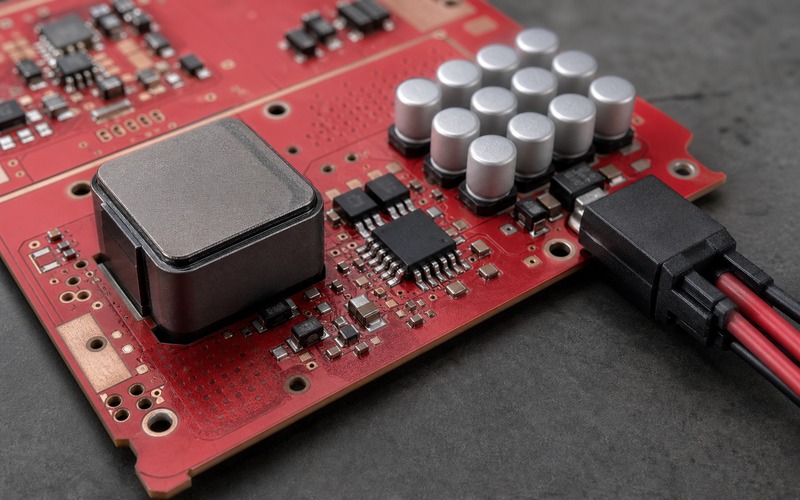
Start With the Real Load Step
Begin with the load event the converter will see on the board. A neural accelerator, FPGA fabric rail, memory rail or wireless processor core can move from idle to active in a short time. The inductor current cannot jump instantly, so the converter response is shared between inductor ramp rate, output capacitance and control-loop bandwidth.
Inductance sets the ripple current and current ramp. A higher value reduces ripple and can ease output capacitor stress, but it slows current movement during a load step and may need a larger magnetic package. A lower value improves current slew and can shrink the part, yet it raises ripple current, peak current, switching loss and noise stress.
The right value is tied to switching frequency, input voltage, output voltage, load current and regulator control mode. A value taken from a reference design can be a good starting point, but the board still needs its own current profile. If input voltage range or switching frequency changes, the same inductor value may no longer give the intended ripple current.
Load-step data should be tied to measurement location. A rail measured at the converter output is not the same as the voltage seen at the processor pins after copper loss, plane spreading and decoupling impedance. The inductor is part of that path, so its review should use the same rail limits and probe method as the final power-integrity check.
Current Rating Is a Set of Conditions
A catalog current rating has to be read with its test condition. Some ratings are based on temperature rise, some on a percentage drop in inductance, and some vendors publish both. A part that looks safe by one rating can be close to saturation under the real peak current, or hot enough to raise nearby capacitor and IC temperature.
Separate average load current from peak inductor current. The inductor carries the DC load plus half the ripple current, and transient conditions can push current higher during recovery. The selected part should keep enough margin at high input voltage, low output voltage, maximum load and maximum ambient temperature, since that combination can produce a severe peak-current case.
Temperature rise rating depends on test board copper, airflow and ambient assumptions. A compact edge device with little copper under the inductor will not cool the same way as a vendor test fixture. A sealed product, camera module, gateway or wearable may trap heat around the magnetic. Check the thermal result in board context before releasing an alternate.
Current rating also interacts with mounting and height. A taller inductor may cool better, but it may collide with a heat spreader, enclosure rib, shielding can or automated optical inspection limit. A lower profile part may fit the enclosure yet carry less current or run hotter. The purchasing rule should keep these tradeoffs visible.
Saturation Behavior Sets the Failure Edge
Saturation is not a clean cliff in every data sheet. Some inductors lose inductance gradually as current rises, while others drop sharply after a threshold. The control loop, current limit and output ripple can react in different ways once inductance falls. The part should be checked near the highest peak current the rail can see, rather than by the printed current rating alone.
A saturated inductor can increase ripple current, heat the winding, stress the MOSFETs and make output capacitors work harder. In a processor rail, that can appear as a reset, a boot failure, a rare inference crash or a rail dip during a load burst. The symptoms may look digital, while the cause is magnetic margin.
Soft saturation can be acceptable when the regulator data sheet and measured rail behavior support it. The key is to compare the saturation curve across the operating temperature range. Core material, geometry and shield design all affect how the part behaves when current and heat rise together.
Short-circuit and startup behavior deserve a separate check. A converter may hit current limit during startup into a large output capacitor bank or during a fault. The inductor must survive that stress without thermal damage, acoustic noise that fails product requirements, or a saturation profile that drives the converter into unstable recovery.
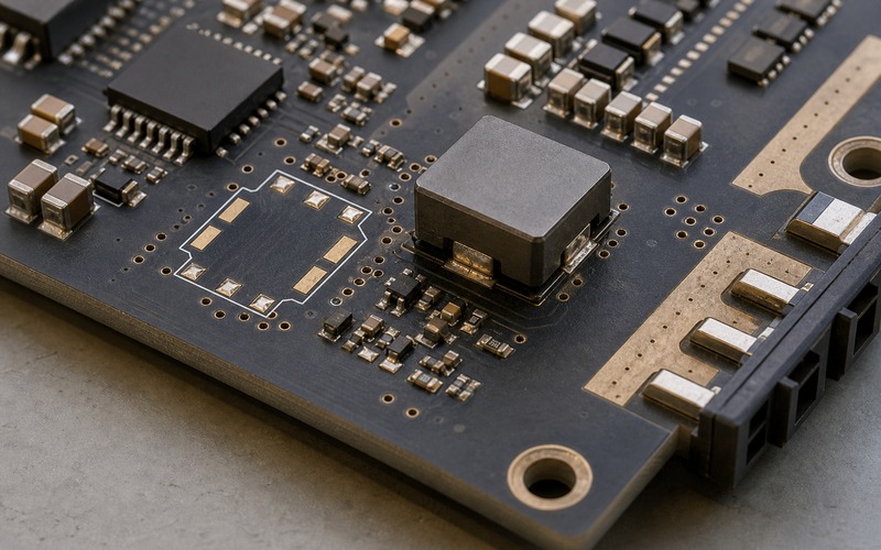
DCR, Core Loss and Temperature Rise Share the Same Trade
DC resistance turns load current into heat. A lower DCR part improves efficiency at high current and reduces temperature rise, but it often needs a larger winding, larger case or different core geometry. A higher DCR part may be smaller and cheaper, yet it can waste power and heat the surrounding PCB area.
Core loss grows with ripple current, switching frequency and flux swing. A part with low DCR can still run hot if its core material is a poor fit for the frequency and ripple profile. High-frequency converters need a loss check that includes both copper and core behavior. Efficiency data from the regulator evaluation board helps, but a dense product layout can change the result.
Temperature affects both the inductor and neighboring parts. A hot inductor beside ceramic capacitors, polymer capacitors, a regulator package or a connector can shorten margin. It can also change DCR and core behavior as the product warms. Infrared photos, thermocouples and repeated load cases give a better view than a room-temperature electrical test alone.
Thermal path is part of the footprint choice. Wider pads, copper pours, thermal vias and airflow can help, but they also change EMI and loop area if placed without care. The layout should keep the switch node compact while still giving the inductor and output current path enough copper to carry heat and current.
Ripple Current Changes Capacitor and EMI Work
Inductor ripple current sets part of the burden seen by the output capacitors. More ripple can require lower capacitor impedance, higher RMS current capability and tighter placement. Less ripple can ease capacitor stress, but it may slow transient response or push the design toward a larger magnetic.
The ripple current also shapes conducted and radiated noise. A shielded inductor can reduce stray field, but shield construction varies. Some shielded parts leak more field than expected around gaps or terminations. A nearby sensor front end, RF section, clock trace or high-gain analog node can expose that difference.
Switch-node layout and inductor placement must be reviewed together. The inductor should not invite a long switch-node copper area, and the output side should connect cleanly to the capacitor bank. A part that fits the pads may still be a poor choice if its termination orientation stretches the noisy loop.
Acoustic behavior belongs in the review for products used near people. Some magnetic parts can sing under pulse-skipping, light-load mode or burst conditions. A converter that is electrically acceptable may still fail a customer experience requirement if the inductor produces audible noise in a quiet room.
Package, Shielding and Placement Are Part of the Part
The package is not a neutral shell. Pad size, termination style, height, shield coverage and body shape decide how the part fits the board and how easily it can be second sourced. A part number substitution should compare land pattern, body clearance, coplanarity, solder fillet access and assembly tolerance before it reaches purchasing.
For compact point-of-load supplies, the inductor often sits near a processor, memory package, connector, shield can or heat spreader. Its height can decide whether a mechanical part fits. Its magnetic field can decide whether a sensitive trace needs more distance. Its footprint can decide whether enough output capacitors can sit close to the rail.
Placement should show a clean current path from regulator to inductor to output capacitor bank and load. The switch node should stay compact, the output copper should carry current without a narrow neck, and the connector or rail entry should face the real cable or power source. A board-edge power connector that opens inward is a mechanical warning sign.
Keep the inductor away from parts that will suffer from heat or field coupling. Hall sensors, magnetometers, precision references, low-level analog inputs and RF sections may need distance or shielding review. The chosen inductor may be electrically correct and still create a placement problem if the product layout has no quiet zone.
Give Purchasing a Controlled Alternate Boundary
An inductor alternate cannot be approved from inductance, footprint and current rating alone. The boundary should include inductance tolerance, saturation curve, temperature-rise current, DCR, core-loss behavior, switching-frequency suitability, shield style, height, footprint, solderability, lifecycle status and approved vendor series.
If the board needs more than one approved source, test candidates in the same converter and board area. Compare output ripple, transient response, efficiency, thermal rise, startup, current limit, light-load behavior, acoustic noise and EMI scan results. A candidate that passes at one load point can fail at another point in the product profile.
The approved list should state what can change without engineering review. A packaging suffix or reel format change may be purchasing work. A lower DCR, different shield style, altered termination, smaller case or different core family should trigger engineering review. Clear boundaries prevent a benign-looking supply change from changing rail behavior.
Record the measurement setup with the release. Include input range, output rail, switching frequency, load profile, probe method, thermal condition, board revision, allowed alternates and any placement limits. That record lets the next buyer or engineer understand why an inductor was accepted rather than treating it as a generic passive line.
Final Inductor Selection Checklist
Before release, check inductance value, tolerance, switching frequency, input and output voltage range, ripple current, average current, peak current, saturation curve, temperature-rise current, DCR, core loss, self heating, footprint, height, shield construction, switch-node layout, output capacitor placement, thermal copper, nearby magnetic sensitivity, acoustic behavior and second-source boundary.
Then check the supply side of the decision. Confirm lifecycle status, package suffix, reel format, approved manufacturers, land-pattern compatibility, process limits, test evidence and the rule for accepting a substitute. Each candidate part should be checked against the real electrical, thermal, mechanical and sourcing conditions it will face before the board moves into production.
A point-of-load inductor looks like a passive part on the bill of materials, but it is a timing, heat and field component inside the power path. Treat it that way and the rail has a better chance of surviving load steps, enclosure heat, production substitutions and long-term purchasing pressure without turning into a late debug item.