Free Shipping Over$200

- Products
- Marking
- Alternative

When Passive Cooling Stops Being Enough for an Accelerator
When Passive Cooling Stops Being Enough for an Accelerator
Passive cooling fails quietly first. The board still boots, the accelerator still answers commands, and the benchmark may pass for a few seconds. Then clock speed drops, latency stretches, error logs appear after warm soak, or the enclosure becomes the part that decides how much inference the product can run.
An accelerator does not care whether the heat path looks tidy in CAD. It cares about junction power, case path, interface pressure, copper spreading, heat-sink area, enclosure temperature and the air that can carry heat away. Passive cooling stops being enough when any one of those links reaches its limit before the workload is finished.
Start With Sustained Power, Not Peak Speed
The first thermal question is not how fast the accelerator can run for a short test. The question is how much power it dissipates during the workload the shipped product will repeat. A vision model that runs in short bursts, a voice model that wakes only on demand and a multi-camera pipeline that stays active for hours create different heat profiles.
Peak power helps size electrical margins, but sustained power sets the thermal burden. A passive heatsink can absorb a short burst and look fine during a quick demonstration. During a warm enclosure test, the same mass becomes saturated and the temperature climbs until the device throttles or the workload must be reduced.
The workload must be named. Frame rate, batch size, model mix, memory bandwidth, pre-processing, radio activity, display output and storage writes all change heat. A board tested with a light demo may fail when the final application keeps the accelerator, memory and power rails loaded together.
Use measurement points that match the product. Board temperature near the package, case temperature, heat-sink base temperature, air temperature inside the enclosure and workload timing all need context. A single external case touch point cannot prove the junction is safe.
Understand the Heat Path From Junction to Air
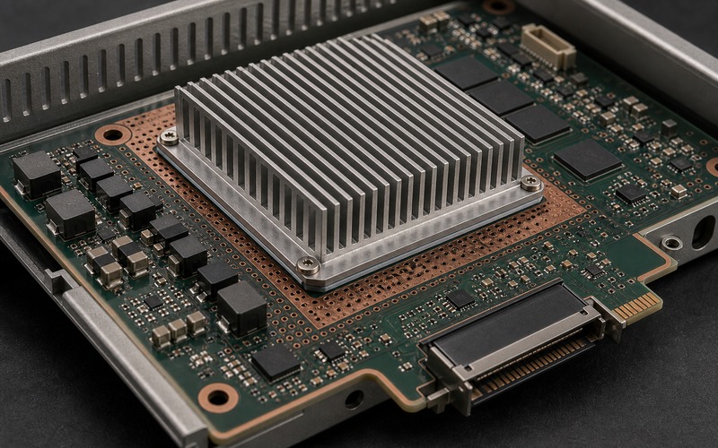
Heat leaves the silicon through several interfaces. It moves from junction to package, from package to lid or exposed pad, through a thermal interface material, into a heat spreader or heatsink, through fins or enclosure metal, and finally into surrounding air. Each layer adds resistance.
A passive design fails when the total path cannot move enough heat at the allowed temperature rise. A large heatsink cannot fix poor contact pressure. A thick thermal pad can fill a gap while adding resistance. A copper pour can spread heat across the board, yet that heat still needs an exit path.
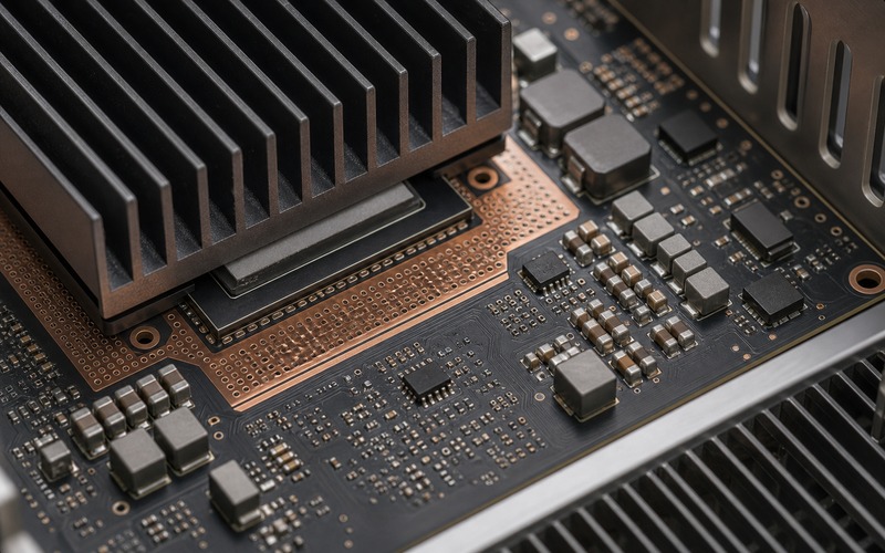
Thermal vias help only when they connect the hot zone to a useful copper area or a metal structure. Blindly adding via arrays can crowd routing, reduce solder reliability or connect heat into a zone that warms another sensitive component. The via field should be tied to a real heat path.
The power components around the accelerator belong in the same review. Regulators, inductors, memory and interface chips heat the local air and board. A passive heatsink sized for accelerator power alone can be underbuilt when the surrounding heat sources run at the same time.
Build a simple thermal-resistance budget before choosing the metal. Estimate the allowed rise from ambient to junction, subtract the internal package path, and leave margin for the interface, spreader, heatsink and enclosure air. The numbers will be approximate, but they expose whether the passive path is plausible before the layout is locked.
Keep electrical margins in the same discussion. Higher temperature can reduce regulator current margin, change oscillator drift, raise leakage current and warm memory or storage next to the accelerator. A passive heatsink that protects the main chip while heating a nearby power part is still an incomplete solution.
Watch the Enclosure Before the Heatsink Looks Full
Natural convection needs space. Tall fins inside a tight box may add metal without adding airflow. If the enclosure wall sits close to the heatsink, air can stagnate and the fin area becomes less effective than the drawing suggests.
Orientation changes the result. A box mounted flat on a table, vertical on a wall, behind a display, under a vehicle dashboard or inside a sealed cabinet sees different air movement. Passive cooling should be checked in the worst expected orientation instead of relying on an open-bench result.
Ambient temperature sets the starting point. A design that survives in a cool room may fail in a warm cabinet, sunlight, a machine enclosure or a fanless industrial panel. The allowed junction limit must be compared against the highest credible local air temperature around the heatsink.
Dust, cable placement and neighboring boards can close the path over time. Passive cooling has no fan to force air through a restricted gap. If the product depends on an open slot, the mechanical design has to protect that slot through assembly, installation and service.
A passive thermal design should be reviewed with the real housing installed. Open-board tests are useful for debugging the heat path, but they hide stagnant air, enclosure radiation, cable shadows, gasket compression and wall temperature. The decision to stay passive belongs to the full product, not the bare PCB alone.
The outside surface also needs a limit. Consumer and handheld products may pass the silicon limit while still feeling too hot to touch. Industrial products can face different limits because they sit near plastic ducts, labels, batteries or service panels. Treat external surface temperature as a requirement, not a side note.
Throttling Is a Design Signal
Throttling is a design signal before it becomes a user-experience issue. It is evidence that the thermal path and workload are competing. When an accelerator drops clock speed, changes voltage, skips work or stretches latency, the product has already left its intended operating point.
Some systems throttle gracefully. Others create timing problems because the camera, sensor, network link or control loop expects a fixed response window. A passive design should be judged by the slowest warm-soaked performance the product can accept, not by the first cold result.
Logs matter. Junction estimates, thermal sensor readings, frequency state, workload duty cycle and rail current tell whether the device is approaching a limit. If only external temperature is measured, the engineering team may miss a die-level limit that appears before the outside feels hot.
A product can also fail without formal throttling. Error rate, image quality, timing jitter, memory errors and local regulator heating can move first. Passive cooling should be checked against system behavior, not a single temperature number.
When the Passive Path Becomes Too Large
A larger heatsink is not always the next answer. It adds height, weight, cost, mounting force and shock load. It can block connectors, antennas, camera FPCs, service access or automated inspection. A larger part can also move heat toward plastic, batteries or temperature-sensitive sensors.
The mechanical stack defines the ceiling. Package coplanarity, thermal-pad compression, screw torque, board bending, heat-spreader flatness and enclosure tolerance decide whether the heatsink touches the part the same way in every unit. Passive cooling can look adequate in one sample and drift across production.
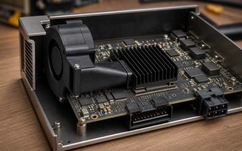
If the required metal volume no longer fits the product envelope, the design has crossed from part selection into architecture. Options include workload duty-cycle reduction, lower-power silicon, a heat spreader tied to the enclosure, guided natural-convection vents, a blower, a larger enclosure or a different board placement.
The right change depends on what limit was reached. If the interface is weak, improve contact. If copper spreading is weak, improve the board path. If enclosure air is stagnant, change venting or airflow. If workload power is too high, change operating policy or silicon choice. Guessing adds metal without solving the limiting link.
Measure Like the Customer Will Use It
Thermal qualification needs the real software load, housing, cable set, orientation, ambient condition and duty cycle. A fan from the lab bench, an open lid, a missing cable or a short test run can hide the failure mode that will return from the field.
Use enough soak time. Passive systems can take a long time to reach steady temperature because metal, board and enclosure mass store heat. A test that stops when the heatsink is still climbing proves little. The temperature trend should flatten or the product should be declared limited by the test window.
Probe setup matters. Thermocouples can disturb contact, infrared readings need emissivity control, and internal sensors may report a filtered estimate. Use several points and record the method so later component or enclosure changes can be compared fairly.
The final report should include workload, ambient, orientation, enclosure state, heat-sink part, interface material, mounting method, board revision, sensor points, maximum observed temperature, throttle state and measured performance at the end of soak. This is the evidence purchasing and engineering need when a substitute heatsink, pad or housing revision is proposed.
Repeat at least one test after assembly variation is represented. A hand-built sample with fresh thermal material and careful screw torque may hide tolerance. Production adhesive thickness, pad placement, screw sequence and enclosure warp can shift contact enough to change the result, so the release evidence should include a realistic build condition.
Set the Boundary for Heatsink and Interface Substitutes
A passive cooling substitute needs more than similar size. The boundary should include fin geometry, base thickness, alloy or material, surface finish, mounting method, flatness, thermal interface thickness, compression range, dielectric requirement, operating temperature range and clearance to nearby parts.
Thermal pads and gap fillers need their own limits. Conductivity values are measured under specific conditions, and thickness or compression can dominate the result. A softer pad may improve contact but reduce mechanical stability; a thinner pad may improve conduction but fail tolerance stackup.
Mounting hardware is part of the thermal design. Clip force, screws, standoffs, springs and adhesive can change contact resistance and board stress. A substitute that matches the heatsink outline but changes mounting force can change both temperature and reliability.
Approve substitutes through temperature and performance tests, not appearance. Compare warm-soaked junction estimate, heatsink base, local board temperature, throttle state and end-of-test performance. If the product has regulatory, safety or touch-temperature limits, those limits must be included in the same review.
Keep a small approved set instead of treating every similar profile as interchangeable. The supplier drawing, tolerance, surface treatment, pad family and fastening method should be tied to test evidence. That boundary helps purchasing avoid a visually similar part that removes the thermal margin the product needs.
Passive Cooling Release Checklist
Before release, check sustained workload power, burst power, duty cycle, junction limit, package heat path, interface material, mounting pressure, copper spreading, thermal-via field, nearby heat sources, enclosure clearance, orientation, ambient range, soak time, throttling behavior and allowed performance at temperature.
Then decide whether passive cooling has margin. If the required heatsink consumes the product envelope, if the enclosure air stagnates, if production tolerance can break contact, or if warm-soaked performance falls below the requirement, passive cooling has stopped being enough for that accelerator.
A passive solution is ready only when the thermal path, mechanical stack and workload are proven together. Otherwise the board may look clean on a bench while the shipped product silently reduces inference speed every time it gets warm.