Free Shipping Over$200

- Products
- Marking
- Alternative

TDK B25696H DC-Link Capacitors for SiC Power Electronics
TDK B25696H DC-Link Capacitors for SiC Power Electronics
TDK has introduced the B25696H* series of MKP DC high-frequency film capacitors for DC-link positions in SiC-based power electronics. The series covers capacitance values from 47 uF to 1280 uF and rated DC voltages from 900 V to 2000 VDC. Its purpose is to give converter designers a DC-link capacitor platform with low parasitic inductance and low ESR where fast SiC switching makes busbar and layout behavior part of the component decision.
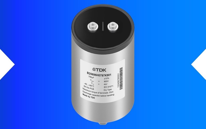
TDK specifies self-inductance as low as 30 nH and ESR down to 0.8 mOhm at 10 kHz, with ESR stability stated up to 100 kHz. These values do not remove the need to validate the finished current path, but they make the B25696H series relevant when a DC-link position must be evaluated together with the switching frequency, laminated-busbar or PCB geometry, and device stress.
What the B25696H series adds to a SiC DC-link design
In a fast-switching converter, the capacitor is part of the commutation loop rather than simply an energy-storage value in the BOM. TDK uses an optimized internal busbar configuration to distribute current homogeneously between the windings. The stated low self-inductance and low ESR are intended to limit parasitic voltage overshoot and resistive loss that can otherwise add electrical and thermal stress to SiC power devices.
| TDK published characteristic | B25696H information | Design-in confirmation |
|---|---|---|
| Voltage and capacitance range | 900 V to 2000 VDC and 47 uF to 1280 uF. | DC-bus operating range, transient envelope, required capacitance at operating conditions, and series or parallel connection strategy. |
| High-frequency behavior | Self-inductance as low as 30 nH; ESR down to 0.8 mOhm at 10 kHz, with stated stability up to 100 kHz. | Commutation-loop geometry, terminal spacing, busbar or PCB inductance, switching edge rate, and measured overshoot at the power device. |
| Ripple-current capability | Up to 91 A at +60 C ambient temperature and 10 kHz. | Actual ripple spectrum, case and hotspot temperature, cooling path, and the applicable rating conditions for the exact part. |
| Mechanical format | Cylindrical MKP capacitor in an aluminum case with resin top; 85 mm or 100 mm diameter, M6 screw-female terminals, and an M12 threaded mounting bolt. | Clearance, mounting torque, vibration environment, busbar arrangement, and service access in the finished assembly. |
Thermal and lifetime conditions belong in the first selection pass
The series is specified for a -40 C to +85 C hotspot operating range. TDK states a lifetime expectancy of 100,000 hours at a +75 C hotspot temperature and the respective rated voltage; with voltage and temperature derating, the stated lifetime can extend to 200,000 hours. Those figures are useful for screening a design, but the final choice needs the application-specific voltage, ripple current, hotspot temperature, cooling arrangement, and mission profile.
TDK also identifies the capacitors as self-healing MKP parts. That property should be reviewed with the full converter fault strategy and the requirement for capacitance retention over life. It is not a substitute for validating the protection system, pre-charge behavior, discharge path, insulation coordination, and expected maintenance interval.
Where the released capacitors fit
TDK lists energy-storage systems, solid-state transformers, renewable-energy inverters, traction drives, and industrial motor drives as typical applications. These are all systems where high DC-bus voltage and fast switching make loop inductance and thermal loading visible at system level. The 85 mm and 100 mm mechanical options give the design team an early way to compare the enclosure and busbar constraints before finalizing the electrical variant.
Practical checks before committing the part number
- Map the measured DC-bus voltage, surge waveform, ripple-current spectrum, and switching frequency to the exact B25696H variant rather than relying on family-level limits.
- Minimize the complete commutation-loop inductance, including terminals, busbar or PCB, semiconductor module, and mechanical spacing. A low-inductance capacitor does not correct a high-inductance layout.
- Model and measure capacitor hotspot temperature under the intended cooling, altitude, and enclosure conditions, then apply the exact voltage and temperature derating guidance.
- Confirm M6 terminal, M12 mounting-bolt, clearance, torque, vibration, and service requirements with the current mechanical drawing for the selected ordering code.
- Validate the protection, pre-charge, discharge, and fault-energy paths with the installed capacitor bank and the final SiC switching behavior.
Related power-stage decisions
DC-link selection works with the rest of the conversion architecture. The TDK E13 EM gate-drive transformer series addresses isolated gate-drive supply requirements in xEV power stages, while onsemi GaNEXUS GaN power devices offer another example of how fast switching changes layout priorities. For a wider component-level review, see Doing solid power conversion for a connected device.
Official source and final confirmation
TDK announced the B25696H* series on June 3, 2026. The official details are in TDK's B25696H DC-link capacitor release. Before the design is frozen, confirm the latest datasheet and mechanical drawing for the exact ordering code, including voltage, capacitance, ripple-current rating conditions, thermal data, lifetime assumptions, terminal details, and the project's qualification requirements.