- Products
- Marking
- Alternative
XC7A35T Accelerating a Small Network on Artix Fabric
XC7A35T Accelerating a Small Network on Artix Fabric
XC7A35T fits designs where the network is small, the timing is tight, and a processor alone leaves too much latency in the path. The part is not a high-end AI accelerator. It is an Artix-class FPGA that can sit beside a sensor, shape the data stream, run a compact fixed pipeline, and hand cleaner results to a host processor. That makes the selection question different from choosing a faster MCU or a larger SoC.
The useful question is whether the design has a narrow, repetitive workload that benefits from fabric. A small classifier, a threshold stage, a feature extractor, a camera line operation, an encoder path, or a trigger filter may fit. A changing model with heavy software libraries may belong somewhere else. XC7A35T earns its place when the board needs deterministic parallel work close to the signal source.
Start with the Workload Size
A small network on FPGA fabric should be described by its real operations, memory movement and input rate. Count the feature width, sample rate, frame line rate, buffer depth and result interval. A vague claim that the network is light does not help a component review. The board record should say what is fixed in hardware and what remains in software.
XC7A35T can make sense when the network is compact enough to fit the available logic, memory blocks and timing budget. It can also make sense when only one stage of the inference path belongs in fabric. A design might place filtering, feature extraction or event detection in the FPGA while the host handles model management, logging and communication.
Do not size the fabric by the demo workload alone. Add margin for interface logic, debug counters, test paths, reset handling and timing closure. A design that fits on paper but leaves no space for visibility or repair can become hard to ship.
Place Fabric Near the Data Source
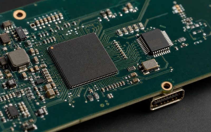
The strongest reason to use a small FPGA is often distance from the signal. If a sensor stream, encoder pulse train or parallel bus arrives at the board edge, the fabric can capture timing before software scheduling enters the path. This is where an Artix part can feel larger than its resource count suggests.
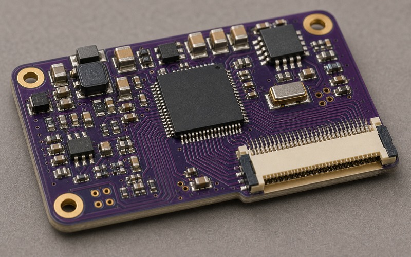
Sensor and debug connectors should face the board edge or the cable path. The picture used for the article follows that rule because connector orientation is not a cosmetic detail. A connector that faces the board center can force a cable over the FPGA, memory or clock region, which is poor evidence for a manufacturable design.
Routing should keep return paths visible. A small network accelerator still depends on clean clocks, stable I/O banks and local decoupling. Short traces from the sensor header to the FPGA may matter more than another unused logic feature.
Review Configuration Memory and Startup
XC7A35T needs a configuration path. The configuration flash, mode pins, programming header, reset supervisor and power ramp belong in the first selection review. Without them the FPGA package is only part of the story. The board must load a known image, recover after power loss, and give production a way to program and verify it.
Startup time should be tied to the product behavior. A wearable sensor, machine fixture or small edge camera may need the capture path ready before the host finishes its own startup. If the FPGA gates a wake signal or safety condition, the configuration time and reset release sequence must be measured.
Keep the programming path reachable after assembly. A hidden JTAG header, blocked cable angle or inaccessible boot strap can turn a recoverable board into a scrap risk during validation.
Power Rails and I/O Banks Set the Board Shape
A small FPGA can still be a demanding power part. Core supply, auxiliary supply, I/O bank voltage, configuration memory, clock source and sensor rail all interact. The current depends on toggle rate, clock frequency, I/O loading and how much of the fabric is active. A low resource design with fast I/O can still stress a small regulator.
Measure rails with the intended bitstream. Bring up should include idle, sensor capture, feature processing, result transfer and reset. Keep the bitstream hash, clock setting and test input with the measurements so a later build can be compared without guesswork.
I/O bank planning must match both electrical and mechanical constraints. Voltage standards, pin groups, package escape, series damping and connector direction should be checked together. A pinout that routes in the lab may become awkward when the sensor cable, enclosure and host connector are added.
Timing Closure Is a Component Risk
For an FPGA selection, timing closure is not a later firmware concern. It is part of deciding whether the component is large enough, fast enough and maintainable enough. Missing constraints can make a failing design look clean, while aggressive constraints can expose routing pressure before the board is frozen.
The selection file should keep the clock plan, generated clocks, input delays, output delays, reset crossings and clock-domain crossings with the design evidence. If the network pipeline crosses from a sensor clock to a processing clock and then into a host interface, each boundary needs an ownership rule and a failure signal.
Debug counters are cheap compared with blind failures. Add counters for dropped samples, buffer full events, clock lock loss, configuration errors and result handoff. When a small network gives a wrong answer, those counters help separate model behavior from capture or timing failure.
Use the Fabric for Fixed Work
The fabric should handle work that is fixed, parallel and close to the input timing. Examples include windowing, thresholding, line buffering, bit packing, trigger detection, lookup stages, compact convolutions or a small feature pipeline. If the model changes every week, the team should keep more of the path in software or choose a different device class.
XC7A35T is often useful as a companion accelerator rather than the only compute element. The host can own communication, updates and model selection while the FPGA owns the narrow path that must run at a fixed rate. This split reduces host jitter without forcing the whole product into programmable logic.
The approval note should state what happens when the algorithm changes. If the feature stage changes shape, can the current fabric still hold it? If the host takes over part of the work, does the link have enough bandwidth? If a larger FPGA is needed, does the package or power plan still fit?
Keep Resource Margin Visible
Resource margin should be recorded in a way that survives design handoff. Logic utilization, block RAM use, DSP use, clock rate, pin use and timing slack all say something different. A small number in one column does not prove the device has enough room. For example, a design may have spare logic while running short on block memory, pin groups or routing channels near a busy I/O bank.
Leave space for error handling and observability. A compact network path still needs state counters, timeout flags, reset controls, test injection and a way to bypass or compare the fabric path during validation. If every spare resource is consumed by the first working bitstream, later fixes can force a device change even when the original calculation looked tidy.
Thermal and power margin should be linked to resource margin. A build that uses more toggling, more I/O activity or a faster clock can move heat into a small region around the FPGA and regulator. The approval record should keep the bitstream, clock plan, input pattern and measured temperature together, so a later revision can explain why current or heat changed.
Document the Tool and Constraint Boundary
FPGA selection depends on the tool flow. The synthesis version, constraint file, pin assignment, timing report, programming method and test image form part of the evidence. If a design passes only on one workstation or with an undocumented project setting, purchasing cannot treat the part as a stable approved choice.
Constraints should be reviewed as engineering input, not as generated background files. Sensor clocks, host clocks, generated clocks, external delays, reset release, false paths and multicycle paths need names a second engineer can understand. When a small network path fails at speed, the first question should be whether the timing evidence matches the board and cable that will ship.
Keep one reduced test build as a reference. It should configure the FPGA, check the clock, move a known pattern through the same I/O pins and return a small result to the host. That build gives the team a stable comparison point when a later model build, new sensor board or replacement oscillator changes behavior.
Substitution Review Is More Than Logic Count
An alternate FPGA is not approved because the logic count is close. Package, speed grade, I/O banks, configuration mode, memory blocks, available tools, power rails, programming flow and lifecycle status all affect replacement risk. Even another Artix part may change pinout, regulator loading or timing closure.
For purchasing, the record should include exact package, speed grade, temperature grade, configuration flash, oscillator, regulator set and allowed alternates. If the product depends on a specific I/O standard, input rate or fabric utilization margin, write that condition next to the part number.
Supporting parts can block the build as easily as the FPGA. Configuration flash, clocks, regulators, level translators and connectors need their own approved options. A sourcing plan that names only the FPGA leaves the board exposed.
Bring-Up Tests Should Prove the Data Path
The first test image should prove power, configuration, clock, a fabric loopback and one real I/O path before the network is judged. A known pattern should enter through the same pins used by the product path and return through the same host interface. That test catches routing, pin, clock and buffer problems before model results muddy the diagnosis.
After that, add the compact network or feature stage. Record the input pattern, expected result, latency and error behavior. A production fixture may use a shorter version, but it should still prove configuration, clock, rail health and at least one fabric-to-host transaction.
Keep the evidence with the board revision. Bitstream hash, tool version, constraints, test image, fixture version and measured limits all belong near the approval record.
Final XC7A35T Selection Checklist
Before approving XC7A35T, confirm workload size, fabric utilization, timing constraints, configuration memory, startup behavior, I/O bank plan, power margins, thermal path, debug access and substitution boundary. Keep body links out of the article unless the target page has been verified as a working page.
The part is a strong choice when a compact fixed pipeline must run close to the signal and the host should stay free for application work. It is a weak choice when the network changes often, the evidence is only a lab demo, or the board cannot prove its timing and configuration path.