 Free Shipping Over$200

- Products
- Marking
- Alternative

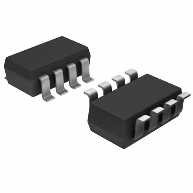
Analog Devices Inc./Maxim Integrated MAX6368LKA29+T
- Part No.:
- MAX6368LKA29+T
- Manufacturer:
- Analog Devices Inc./Maxim Integrated
- Category:
- Supervisors
- Package:
- SOT-23-8
- Datasheet:
-
 MAX6368LKA29+T.pdf
- Description:
- IC SUPERVISOR MPU LP SOT23-8
- Quantity:
Unit Price:$0.000000
Ext Price:$0.000000
- Payment:

- Shipping:

Inventory:2,470
Send us your inquiry,we will respond immediately.
In Stock : 2,470 PCS
| Qty. | Unit Price | Ext Price |
| 0+ | $0.000000 | $0.000000 |
*Products eligible for online ordering ship within 1-2 business days,please contact us for exact shipping times.
Also you can RFQ for MAX6368LKA29+T or email to us: Email: [email protected] , we will contact you within 12 hours.
Product Details
MAX6368LKA29+T - Maxim MAX6368 µP Supervisor with Battery Backup & Chip-Enable Gating, 2.93 V Reset, Adjustable RESET IN, 8-Pin SOT23 | MAX6368
MAX6368LKA29+T is the lead-free, tape-and-reel 8-pin SOT23 version of Maxim's MAX6368, a low-power microprocessor (µP) supervisory circuit with battery-backup switchover and chip-enable gating. It monitors the supply against a 2.93 V reset threshold (the "29" code) and asserts a push-pull RESET (L grade) for at least 150 ms; it switches the backup output between VCC and a battery on power-fail, and gates the chip-enable to write-protect external CMOS RAM. An auxiliary user-adjustable RESET IN monitors a second voltage. Operating down to 1.2 V (VCC or VBATT), it suits critical µP/µC power monitoring, industrial control, computers/controllers and battery-backed equipment.
Product Introduction
The MAX6365-MAX6368 from Maxim Integrated (now part of Analog Devices) are low-power µP supervisory circuits that do three jobs at once: monitor the supply and hold the processor in reset until it is valid, switch a backup battery in when the main supply fails, and gate the chip-enable so external CMOS RAM cannot be corrupted during a power transition. The MAX6368 is the version with an auxiliary user-adjustable RESET IN. MAX6368LKA29+T is the RoHS ("+"), tape-and-reel ("T") option in 8-pin SOT23; the "29" sets the reset threshold at 2.93 V and the "L" selects the push-pull RESET output.
The supervisor watches VCC against the factory-trimmed 2.93 V threshold. When VCC falls below it - on power-up, power-down or a brownout - the device asserts RESET and holds it for a guaranteed 150 ms minimum after VCC recovers, giving the processor a clean start. The RESET/RESET̅ outputs are valid down to 1.2 V of VCC or VBATT, so the reset stays asserted even as the rail collapses. Power-supply transient immunity prevents false resets on short glitches.
For non-volatile memory, the battery-backup and chip-enable gating work together. The OUT pin powers the RAM from VCC normally and switches to the BATT input when the main supply fails, so data is retained. At the same time, the supervisor passes the processor's CE IN through to CE OUT only while the supply is valid - blocking writes during power transitions to protect memory contents. The MAX6368 adds the auxiliary RESET IN comparator so a second voltage (a different rail or a divided input) can also force a reset.
Expert Technical Insight
How is the supervisor applied, and what should the designer mind?
- Pick the threshold and output style by part code: the "29" is the 2.93 V reset threshold and "L" is push-pull RESET; other suffixes give different thresholds and open-drain RESET̅ or RESET options. Match the threshold to the processor's minimum operating voltage with adequate margin.
- Wire battery backup and CE gating correctly: route the RAM's supply from OUT (not directly from VCC) so it follows the switchover, connect the coin cell to BATT, and pass the memory's chip-enable through CE IN -> CE OUT so writes are blocked during power transitions. This is what actually protects the data.
- Use RESET IN for a second rail: the auxiliary user-adjustable RESET IN lets the MAX6368 also monitor another voltage via an external divider - tie it to VCC if unused. The whole part runs down to 1.2 V on VCC or VBATT, so the reset and backup remain valid as the supply decays.
Key Benefits
Monitors VCC against a factory-trimmed 2.93 V threshold and holds RESET for a guaranteed 150 ms minimum for a clean processor start.
OUT powers CMOS RAM from VCC and switches to the BATT input on power-fail, retaining data through an outage.
Passes CE IN to CE OUT only while the supply is valid, write-protecting external memory during power transitions.
Auxiliary user-adjustable RESET IN monitors a second voltage; valid to 1.2 V VCC/VBATT, in 8-pin SOT23.
Specifications
| Parameter | Value | Condition / Note |
|---|---|---|
| Device Type | µP Supervisor (Battery Backup + CE Gating) | MAX6368: adjustable RESET IN |
| Manufacturer | Maxim Integrated (Analog Devices) | MAX6368 |
| Reset Threshold | 2.93 V | "29" code; factory-trimmed |
| RESET Output | Push-pull RESET | "L" grade (active style per code) |
| Reset Timeout | 150 ms min | After VCC recovers |
| Battery Backup | OUT switches VCC / VBATT | Powers CMOS RAM |
| Chip-Enable Gating | CE IN -> CE OUT (gated) | Memory write protection |
| Auxiliary Input | RESET IN (user-adjustable) | Monitors a second voltage |
| Min Operating Voltage | 1.2 V | VCC or VBATT; RESET valid |
| Transient Immunity | Yes | Rejects short glitches |
| Supply Current | Low (µA class) | Battery-friendly |
| Operating Temperature | -40 to +85 °C | Extended (L grade) |
| Package | 8-Pin SOT23 | |
| Orderable Part Number | MAX6368LKA29+T | Pb-free, tape and reel |
Note: Values are taken from the Maxim MAX6365-MAX6368 datasheet. Confirm every parameter (especially the exact threshold and RESET polarity for the LKA29 code) against the latest official documentation before committing a design.
Package Information
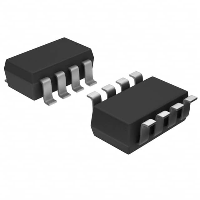
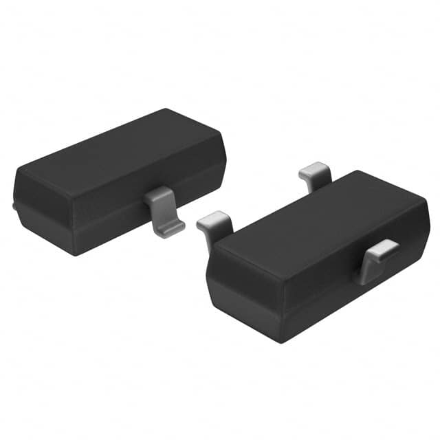
MAX6368LKA29+T ships in the 8-pin SOT23 - the small surface-mount body that lets a full supervisor with battery backup and CE gating sit beside the processor and its CMOS RAM. Keep the BATT trace clean to the coin cell, route the RAM supply from OUT, and pass the memory chip-enable through CE IN/CE OUT. Bypass VCC at the pin. The package image is shown below.
Pin and Signal Definition
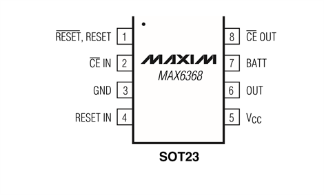
The 8-pin SOT23 carries the reset, battery-backup and chip-enable signals (MAX6368 pin configuration, per the MAX6365-MAX6368 datasheet):
- Pin 1 - RESET̅/RESET: Reset output (push-pull on the L grade); asserted while VCC is below threshold and for 150 ms after.
- Pin 2 - CE IN: Chip-enable input from the processor.
- Pin 3 - GND: Ground.
- Pin 4 - RESET IN: Auxiliary user-adjustable reset comparator input (monitors a second voltage); tie to VCC if unused.
- Pin 5 - VCC: Main supply input (monitored).
- Pin 6 - OUT: Backup-switched output to CMOS RAM (VCC normally, VBATT on power-fail).
- Pin 7 - BATT: Backup-battery input.
- Pin 8 - CE OUT: Gated chip-enable output to memory (blocked during power transitions).
Alternative and Related Parts
Within the MAX6365-MAX6368 family the variants differ by feature: the MAX6365 has a manual-reset input, the MAX6366 a watchdog, the MAX6367 a battery-on output and power-fail comparator, and the MAX6368 (this part) the auxiliary RESET IN. Related power-management parts are listed below.
| Part Number | Brand | Type / Relation | Package | Note |
|---|---|---|---|---|
| MAX604CSA+T | Maxim | 3.3 V LDO regulator | 8-SO | Companion supply |
| MAX6071BAUT33+T | Maxim | 3.3 V precision reference | 6-SOT23 | System reference |
| MAX6063BEUR+T | Maxim | 3.0 V voltage reference | SOT23-3 | Reference |
| MAX5921EESA+ | Maxim | -48 V hot-swap controller | 8-SO | Power-path control |
| MAX5980GTJ+T | Maxim | Quad PoE PSE controller | TQFN | Power delivery |
Selection Tips: Choose the MAX6368 when you need a µP supervisor with battery backup, chip-enable gating and an auxiliary adjustable RESET IN at a 2.93 V threshold. Within the family the MAX6365 (manual reset), MAX6366 (watchdog) and MAX6367 (battery-on/power-fail) cover other feature sets; the threshold and RESET polarity are set by the part-code suffix.
Manufacturer Information
Maxim Integrated, now part of Analog Devices, Inc. (ADI), built the MAX6365-MAX6368 to combine reset supervision, battery-backup switchover and memory write-protection in one SOT23 - the housekeeping a microprocessor system needs to start cleanly and keep its data through a power loss.
ADI maintains the datasheet, the threshold/timeout/polarity option tables and the battery-backup and CE-gating application guidance for the family - the documentation behind a reliable supervisory design.
Applications



Frequently Asked Questions
What does MAX6368LKA29+T do?
It is a µP supervisor: it monitors VCC against a 2.93 V threshold and asserts RESET (for 150 ms after recovery), switches a backup battery to power CMOS RAM on power-fail, and gates the chip-enable to write-protect that memory. The MAX6368 also has an auxiliary user-adjustable RESET IN. The "L" code is push-pull RESET; "29" is the 2.93 V threshold.
What is chip-enable gating for?
It protects external CMOS RAM. The processor's chip-enable passes from CE IN to CE OUT only while VCC is valid; during power-up, power-down or a brownout the gate blocks CE OUT, so no accidental write can corrupt the memory contents that the backup battery is preserving.
How does the battery backup work?
The OUT pin powers the RAM from VCC while the supply is good and automatically switches to the BATT input when VCC fails, so data is retained. The part operates down to 1.2 V on VCC or VBATT, keeping the reset and switchover valid as the supply decays.
What is the RESET IN pin?
It is an auxiliary user-adjustable reset comparator input, unique to the MAX6368 in this family. Drive it from an external divider to monitor a second voltage; if either VCC (at 2.93 V) or RESET IN goes out of range, the device asserts reset. Tie RESET IN to VCC if it is not used.
Disclaimer
Information Accuracy: The specifications on this page are based on the official Maxim MAX6365-MAX6368 datasheet. We work to keep the information accurate and complete, but parameters can change with product revisions, so design engineers should verify all values against the latest official documentation before final design.
Product Authenticity Guarantee: All parts we supply are genuine factory originals with full material traceability.
Technical Support: Pre-sales and post-sales technical consultation is available free of charge.
Application Notice: This page is for reference only. Suitability for a specific application should be confirmed by the design engineer against the actual system requirements.
MAX6368LKA29+T Specifications
- Specifications
- Attributes
- Property Value
- Manufacturer
- Analog Devices Inc./Maxim Integrated
- Series:
- -
- Package/Case:
- SOT-23-8
- Packaging:
- Tape & Reel (TR)
- Part Status:
- Active
- Programmable:
- Not Verified
- Type:
- Battery Backup Circuit
- Voltage - Threshold:
- 2.93V
- Output:
- Push-Pull, Totem Pole
- Reset:
- Active Low
- Reset Timeout:
- 150ms Minimum
- Operating Temperature:
- -40°C ~ 85°C (TA)
- Number of Voltages Monitored:
- 1
- Grade:
- -
- Qualification:
- -
- Mounting Style:
- Surface Mount
- Supplier Device Package:
- SOT-23-8
- Category:
- Supervisors
MAX6368LKA29+T Relevant information
- MAX6368LKA29+T Tags
- Popular Search
The following parts are popular search parts in Supervisors.
The Posts
-
STM32F407VET6 STMicroelectronics MCU Selection Guide
STM32F407VET6 guide covering Cortex-M4 use, 512KB Flash, LQFP100 pinout checks, alternatives and sourcing notes.
-
STM32F103C8T6 STMicroelectronics MCU Selection Guide
STM32F103C8T6 guide covering Cortex-M3 use, 64KB Flash, LQFP48 pinout checks, alternatives and sourcing notes.
-
STM32F405RGT6 STMicroelectronics MCU Selection Guide
STM32F405RGT6 guide covering Cortex-M4 use, 1MB Flash, LQFP64 pinout checks, alternatives and sourcing notes for engineers.
-1,80mm.jpg)
-
GRM31CR61H106KA12L Murata MLCC: Applications, Selection and Buying Notes
GRM31CR61H106KA12L Murata MLCC guide for 10uF 50V X5R 1206 use, obsolete-status review, alternatives and sourcing checks.
-
GRM31CR61E476ME44L Murata MLCC: Applications, Selection and Buying Notes
GRM31CR61E476ME44L Murata MLCC guide for 47uF 25V X5R 1206 decoupling, alternatives and sourcing confirmation.
-2,70mm.jpg)
-
GRM32ER71H106KA12L Murata MLCC: Applications, Selection and Buying Notes
GRM32ER71H106KA12L Murata MLCC guide covering applications, selection, alternatives and sourcing checks for 10 uF, 50V, X7R, +/-10%, 1210 MLCC.
-0,55mm.jpg)
-
GRT155C81E105KE13D Murata MLCC: Applications, Selection and Buying Notes
GRT155C81E105KE13D Murata MLCC guide covering applications, selection, alternatives and sourcing checks for 1 uF, 25V, X6S, +/-10%, 0402 automotive MLCC.
-
GRM155C81E105KE11D Murata MLCC: Applications, Selection and Buying Notes
GRM155C81E105KE11D Murata MLCC guide covering applications, selection, alternatives and sourcing checks for 1 uF, 25V, X6S, +/-10%, 0402 MLCC.
Related Products
-
MIC826SYMT-TR
Microchip Technology
-
APX803S-31SA-7
Diodes Incorporated
-
APX803L20-29SA-7
Diodes Incorporated
-
TPS3828-33DBVR
Texas Instruments

-
V6340RSP3B+
EM Microelectronic

-
EM6325CXSP5B-2.9+
EM Microelectronic
-
MCP120T-300I/TT
Microchip Technology
-
MCP130T-315I/TT
Microchip Technology
-
MCP120T-475I/TT
Microchip Technology
-
MCP111T-300E/TT
Microchip Technology
-
MCP120T-315I/TT
Microchip Technology
-
MCP809T-315I/TT
Microchip Technology


