 Free Shipping Over$200

- Products
- Marking
- Alternative

Choosing LDO and DC DC Parts for Each Power Rail
A power tree is not a list of voltages. It is a set of compromises about noise, heat, transient load, dropout, startup order, battery range and fault behavior. The same connected device may need a quiet analog rail, a pulsed radio rail, a logic rail, a display rail, a sensor excitation rail and a high input pre-regulator. Treating every rail as a generic 3.3 V or 1.8 V output is how a board gets hot, resets during transmit, reads a noisy sensor or fails when the input adapter changes.
P3.25 groups the power parts by job. Linear regulators serve quiet or small rails when heat is acceptable and noise matters. Buck converters take a higher rail down with efficiency when current is real. Boost converters and charge pumps create rails that the battery or main bus cannot provide directly. Larger controllers and power management ICs handle front-end or higher current work. The part number should follow the rail requirement, not the other way around.
Quiet rails start with current, dropout and noise
A small LDO is often used because it looks clean and easy. It is only clean if the current, dropout, stability and thermal budget fit the circuit. TLV74033PDBVR as a 3.3 volt compact LDO and TLV74018PDBVR as a 1.8 volt compact LDO belong near the small local rail discussion. They can feed a sensor, logic island or quiet support circuit, but the upstream rail has to stay high enough for dropout and the package has to shed the voltage difference as heat.
Noise becomes the next filter. LP5912-1.8DRVR as a low noise 1.8 volt LDO and TPS7A9201DSKR as a low noise LDO are chosen when the rail feeds analog, RF, clocking or ADC reference support. The regulator data sheet should be read with the output capacitor, load current and frequency band of interest in mind. A low noise claim at one condition does not guarantee a quiet board if the bypass network, ground return or upstream converter ripple is wrong.
Older or higher voltage rails have their own tradeoffs. LM1117IMPX-3.3 as a common 3.3 volt LDO and LD1117-3.3 as a classic 3.3 volt LDO are familiar, but familiarity does not remove dropout or heat. XC6241B2519R-G as a high input voltage LDO is a different answer when the upstream rail is high. ISL80103IRAJZ-TK as a 3 amp LDO and TPS7A5301WQRTKRQ1 as an automotive high current LDO show that an LDO can carry serious current, but at that point thermal resistance and input-output voltage difference become the first calculation. L78S15CV-DG as a 15 volt linear regulator belongs to the higher voltage linear rail side, where package, heat sink path and load profile matter more than the simplicity of the symbol.
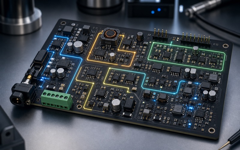
Buck converters are chosen by the load step, not only efficiency
A buck converter becomes the natural choice when the voltage drop is large or the current is too high for a linear regulator. TPS563201DDCR as a compact buck converter and TPS564242DRLR as a buck converter fit compact step-down rails. The selection should start with input range, output current, switching frequency, compensation style, minimum on time, light load mode and the load step the rail will see. A radio or processor rail can demand current in short bursts, and the converter has to recover without pulling reset or ADC reference rails with it.
Multiple rails can be created from one package when the timing and load make sense. TPS62402DRCT as a dual buck converter belongs in that space. Dual regulators can save area and align startup behavior, but they also place two rails in one thermal and layout neighborhood. The inductor placement, feedback routing and ground split matter. If one rail feeds noisy digital logic and the other feeds a sensitive block, the physical layout may decide whether the dual solution is elegant or troublesome.
Wide input designs need a different review. MP9486AGN-Z as a wide input buck, RT8279GSP as a Richtek buck converter, SY8105IADC as a Silergy buck converter, LMR14050SSQDDARQ1 as a wide input industrial buck and EUP3284HWIR1 as a buck converter all point toward different input, current and sourcing choices. The design should compare transient voltage, input protection, duty cycle limits, diode or synchronous behavior, inductor saturation, thermal rise and EMI scan risk. SiC438AED-T1-GE3 as a buck with an integrated power stage adds another path, integrating more of the switch stage so current loops can be compact if the layout follows the part's intent.
Boost rails and charge pumps need load honesty
A boost converter is tempting when a battery can drop below the rail the device needs. It should be chosen from the lowest input voltage, peak switch current, inductor saturation and output load, not from the output voltage alone. TLV61070ADBVR as a boost converter and TPS613221ADBVR as a compact boost converter cover this low input to useful rail problem. At low battery voltage, input current rises. A load that looks modest at 3.3 V can become a harsh demand on a nearly empty cell.
Control mode and light load behavior matter for battery products. A boost rail feeding a sensor may need low ripple. A rail feeding a display may need pulse current tolerance. A rail feeding a radio assist circuit may need fast response. If the converter enters a light load mode that produces ripple in the band the sensor reads, the measurement can move. If the inductor saturates during a pulse, the rail collapses and the firmware sees a mystery reset. The converter, inductor and input capacitor are one selection.
Not every odd rail needs an inductor. TPS60400DBVR as a charge pump inverter can create a small negative rail when the load is light and predictable. Charge pumps avoid an inductor, but they have output resistance, switching ripple and current limits. They work well for bias rails, analog support and small signal needs, not for pretending a real power rail exists where the load is dynamic and heavy.
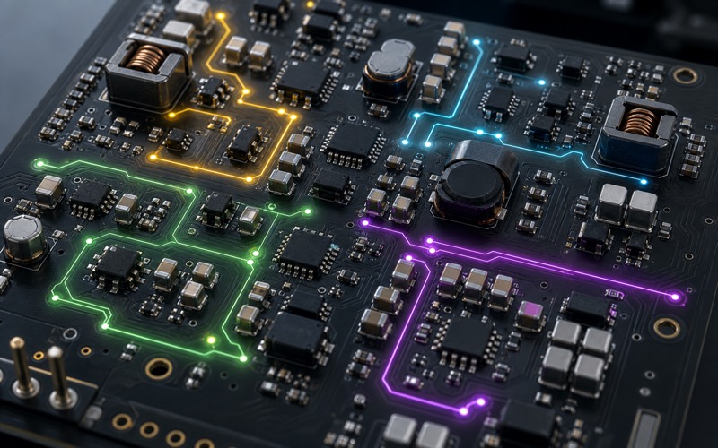
Front-end and higher current parts shape the whole input path
Some power parts are not chosen for a small local rail. They sit closer to the system input or a larger power function. HT7610A as a Holtek power chip and HT7612B as a Holtek power chip should be judged by the surrounding application circuit rather than by name alone. MP5496GR0002-Z as an MPS power management chip belongs in a power management discussion where sequencing, integration and system load behavior are linked. NCP1605DR2G as a power factor correction controller is even farther upstream, where input stage, compliance and power architecture define the design.
Those parts should be placed into a power plan before layout. What input source is allowed, what surge or adapter behavior appears, which rails start first, which rails can be disabled, which loads pulse together, which rail is allowed to be noisy, and where heat leaves the enclosure. A PMIC or controller cannot be judged only by the output table. It has to fit the system's boot path, fault path and supply chain path.
Sequencing is a hidden part of that plan. A radio module may require its IO rail before its core rail, or the reverse. A sensor may need excitation before the ADC reads, yet should not be powered during deep sleep. A processor may back power a disabled peripheral through a GPIO if the rail order is wrong. A display rail may create a visible flash if it starts before the controller owns the enable pin. The regulator data sheet rarely knows those relationships. They are system rules, and the enable pins, pull states, discharge resistors and reset timing have to enforce them.
Protection belongs in the same conversation. A wide input buck may need a TVS, fuse, reverse polarity element or inrush limit before it. An LDO feeding an external sensor may need current limiting or a series element at the connector. A boost rail tied to a rechargeable cell may need undervoltage behavior that does not damage the cell. A charge pump used for a bias rail may need a discharge path so the analog circuit does not stay half biased after shutdown. Power protection should be checked by fault current and recovery state, not only by survival.
Thermal testing should be planned before the board is sent out. The hot condition may not be full load on every rail. It may be high input voltage into an LDO, low battery voltage into a boost, several buck rails pulsing at once, an enclosure with no airflow, or a charger adapter at the edge of its tolerance. A quick infrared check during one bench mode can miss the real operating point. Each regulator should have a defined heat path and a test condition that proves the path works.
Measurement rails need a different kind of proof. A clean 1.8 V analog rail should be checked under the switching pattern used in the final product, not with the radio and display disabled. A buck feeding digital logic should be checked for ripple coupling into the sensor ground. A reference support LDO should be checked during wake and sleep transitions. If the firmware averages readings, the electrical noise can hide inside a number that looks stable. The rail review should include the measurement setup that will reveal coupling, not average it away.
Choose the rail, then choose the regulator
The durable sequence is to write the rail requirement first. Voltage, tolerance, load range, peak current, standby current, noise band, transient response, startup order, discharge behavior, thermal limit and fault action. After that, the category becomes clear. A quiet small rail may use an LDO. A hot or higher current rail needs a buck. A battery product may need a boost for one function and an LDO for another. A small negative rail may use a charge pump. A system input may need a controller or PMIC. When those decisions are made by rail behavior, the part numbers in this list become useful options instead of a pile of similar looking regulators.
That order also makes substitutions safer. A replacement LDO must preserve dropout, stability, noise and thermal behavior. A replacement buck must preserve compensation, current limit, switching behavior and layout requirements. A replacement boost must survive the lowest input voltage. A replacement charge pump must meet ripple and load limits. A replacement PMIC must preserve sequencing. Power parts rarely fail politely; they reset the product, heat the enclosure or corrupt measurements. Treating each rail as its own engineering problem is the only way to keep those failures out of the field.






