 Free Shipping Over$200

- Products
- Marking
- Alternative

Fitting a Battery Device With Charging and Cell Parts
A battery product is often drawn as a cell, a charger and a load. Real hardware is less tidy. The product may need to run while the adapter is attached, charge without heating the enclosure, wake from a dead cell, protect a tiny connector, keep time from a coin cell, and report enough state that firmware does not make the wrong decision. A charger IC is part of that job, but it is not the whole job. The cell, the charge current, the power path, the thermal path, the connector and the standby load have to agree with each other.
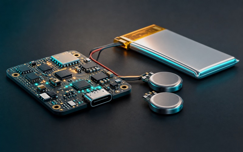
P3.26 groups the charging and cell parts by the job they solve in a connected device. Some boards need a small single-cell linear charger. Some need a charger that can separate the system rail from the battery during adapter operation. Some need a tiny charger for a wearable, tracker or sensor tag. Some do not need a full battery pack at all, but they do need a rechargeable coin cell for backup timekeeping or small standby storage. The right part number starts with the operating case, not with the package drawing.
Linear charging is clean when the heat budget agrees
LTC4054ES5-4.2 for single cell lithium linear charging belongs in the plain single-cell charger discussion. A linear charger is attractive because the circuit is compact, the current path is easy to understand, and EMI risk is lower than with a switching stage. It can be the right answer for a small lithium-ion or lithium-polymer product charged from USB or a regulated input, as long as the difference between input voltage and cell voltage can be burned as heat.
That heat check has to be done at the worst part of the charge curve, not at the neat condition on the schematic. When the cell is low and the adapter sits high, the charger package carries the voltage drop at the selected current. A board in open air may pass. The same board inside a sealed plastic case, next to a radio and a warm processor, may reduce charge current or run hotter than the product team expected. The charge current should be chosen from the enclosure and user touch limit as much as from the cell capacity.
The input source matters as well. A USB connector, a pogo-pin cradle and a small wall adapter are not the same source. Cable drop, adapter tolerance, connector resistance and ESD parts all sit before the charger. If the charger input collapses during charge, the device may cycle, the charge timer may restart, or the system rail may dip. A clean linear charger layout still needs a controlled input path, local capacitance and a ground return that does not push charge current through the sensitive analog area.
Power path management decides what happens while plugged in
A product that can run from the adapter while charging needs a different review. MP2770GL-0000-Z as a charger with power path management points to that class of solution. Power path management is not a cosmetic feature. It decides whether the system load steals charge current, whether the battery is exposed to the full adapter behavior, whether the product can boot from a low cell, and how the system rail behaves when the cable is inserted or removed.
Without a managed path, the battery and system load can fight each other. A radio burst may pull current from the same node the charger is using to measure the cell. A processor may boot, brown out, and boot again if the cell is low. The user may plug in a product that looks alive on the adapter, then watch it die when the cable is pulled because the battery never reached a usable state. The charger should make the boundary clear: which current goes to the system, which current goes to the cell, and which limit protects the input source.
BQ24079TRGTR for lithium charging with a system power path belongs in the same operating case. The phrase system power path should make the designer ask bench questions. Can the product start when the battery is deeply discharged? What is the system voltage before the cell enters normal regulation? What happens if the radio transmits while the adapter is current limited? Does the charger reduce charge current to keep the input alive? Does firmware see a stable power-good signal, or only a rail that looks acceptable until a load pulse arrives?
These questions matter in field products because charging is often the first user-visible electrical mode. A sensor tag may be asleep for months, then placed on a cradle. A handheld device may be used while charging. A gateway backup pack may be charged during normal line power and then asked to carry the load during an outage. A charger with power path behavior should be verified with the actual firmware load profile, not only with an electronic load set to a constant current.
Layout is part of the decision. The adapter input loop, charger power path, battery connector, sense path and system rail bypassing should not be spread across the board because the schematic symbol looked small. If the battery connector sits far from the charger, the sense point and the current path can disagree. If the system rail branches before adequate local capacitance, the processor may see cable insertion as a reset event. If the charge current crosses under a sensor or reference circuit, the measurement may move during charge. A power path charger earns its value only when the physical board respects the paths it creates.
Tiny chargers are selected by the average life of the product
BQ25180YBGR as an ultra compact single cell charger fits the other end of the problem. A small wearable, tag, locator or sealed sensor may not have board area for a large charger block. It may charge at a modest current, sleep for long periods, and care as much about leakage and shutdown state as about charge speed. In that class of product, a tiny charger is not chosen only to save area. It is chosen because every microamp around the battery becomes part of shelf life and field life.
The smaller the product, the less margin there is for lazy assumptions. The cell may be a small pouch with strict charge current. The connector may be a magnetic dock or a pair of pads. The thermal path may be a thin plastic shell. The firmware may spend nearly all its life in standby, waking only for a motion event, BLE advertisement or sensor sample. A charger that behaves well at room temperature on a bench still needs to be checked at low cell voltage, high adapter tolerance, warm enclosure, and the deepest sleep state the product uses.
The charger also has to cooperate with production. A factory may receive cells at different states of charge. Some boards may sit in inventory. Some devices may be programmed before the cell is connected. Some may ship with a shipping mode enabled. The charging IC and the firmware have to handle that flow. If the product cannot wake from a depleted cell without special handling, support cost rises. If the product cannot stay off while attached to a charger during a fixture step, factory timing changes. A small charger part can create large process questions.
Charge status pins deserve attention. They often end up treated as a user LED driver or a spare input to the controller, yet those pins may define the product's behavior on a cradle. The LED current, pull-up rail, logic threshold and sleep state have to be checked. If a status pin back powers a sleeping controller, the battery budget changes. If a charge-complete indication is sampled through a noisy rail, firmware may report false states. Small products are unforgiving because every pin is reused.
Rechargeable coin cells solve backup jobs, not main power jobs
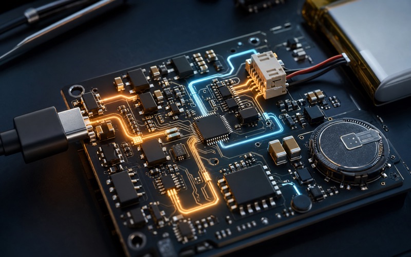
VL-2330HFN as a rechargeable vanadium lithium coin cell and ML414H-IV01E as a rechargeable manganese lithium coin cell move the discussion from main product power to backup energy. These parts are often used to keep an RTC, small memory, security state or low-current backup domain alive when the main supply is removed. They should not be treated as small versions of a lithium pouch cell. Capacity, charge method, leakage, allowable charge current and lifetime assumptions are different.
The backup load has to be measured before the cell is chosen. An RTC at a few hundred nanoamps is one job. A backup SRAM, security element, wake detector or leakage-heavy board is another. The board may look asleep while a divider, ESD structure, pull-up or protection path leaks enough current to drain a tiny rechargeable coin cell. The only honest number is the current from the backup node in the final board state, across temperature and with the main power removed.
Charging the backup cell also needs restraint. A rechargeable coin cell may be topped from the main rail through a resistor, diode arrangement or charger circuit, depending on the chemistry and limits. The designer has to check the allowed float voltage, maximum charge current, reverse leakage and what happens when the main rail is present for years. A backup cell that survives a one-week bench test can still be mistreated across a product's service life if it is held at the wrong voltage or charged from an uncontrolled rail.
Placement is not glamorous, but it matters. A coin cell backup path should avoid heat from chargers, regulators and radios because temperature shortens life and changes leakage. The mechanical retention, solder tabs and service expectation should be clear. If the cell is soldered, replacement may not be part of the service plan. If it uses a holder, vibration and contact resistance become part of the design. A backup energy source is quiet until the day the main supply disappears; then it becomes the only thing preserving time or state.
Write the charge case before choosing the part
The selection sequence should start with a written charge case. Cell chemistry and capacity. Input source and connector. Maximum adapter voltage and current limit. Desired charge current. Product operation during charge. Deep-discharge recovery. Battery absent behavior. Thermal limit. Sleep current. Shipping mode. Status reporting. Backup domain load. Service life. Once those are known, the part class becomes clearer. A simple small product may use a linear charger. A device that operates while plugged in may need a managed system power path. A tiny wearable may need an ultra compact charger with careful standby behavior. A clock or memory domain may need a rechargeable coin cell rather than a main pack.
Substitution should follow the same map. A replacement charger is not equivalent because it shares a package and charge current. It must preserve termination behavior, precharge threshold, thermal regulation, input current behavior, status pins, battery absent mode and layout constraints. A replacement power path charger must preserve how the system rail behaves during cable insertion, low battery and load pulses. A replacement rechargeable coin cell must match chemistry limits, charge method, capacity, dimensions and tab arrangement. Battery hardware has long memory: the effect of a small mismatch can appear months later as short runtime, swollen cells, lost timekeeping or a product that cannot wake from a dead battery.
The practical gate is simple to state and demanding to pass. Test the charger with a low cell, full cell, missing cell, current-limited adapter, warm enclosure, sleeping firmware, active radio load and cable removal. Measure the backup current on the actual board. Check that the cell temperature and charger package temperature stay within the product's rule, not just the IC's absolute rating. Confirm that the connector faces the edge and that protection sits near the entry. Then write the approved part number. A battery product feels reliable when the user never notices this work, and that only happens when the charging path has been engineered as part of the system.






