 Free Shipping Over$200

- Products
- Marking
- Alternative

DS18B20 on a One Wire Temperature Bus
DS18B20 on a One Wire Temperature Bus
DS18B20 is a digital thermometer with a 1-Wire interface, a unique 64-bit ROM identity, programmable resolution and nonvolatile alarm thresholds. One bus master can communicate with one sensor or address many sensors on the same data conductor. The device measures from -55 to +125 degrees Celsius, with specified accuracy of plus or minus 0.5 degree Celsius from -10 to +85 degrees Celsius.
The small pin count can make the circuit look trivial: a host pin, a pull-up resistor, a sensor and ground. Reliable operation still depends on power mode, cable capacitance, topology, timing, identification, CRC checking and thermal installation. A stainless probe assembly also adds cable, sealing and sourcing questions that are outside the bare IC specification. Each layer should be verified on its own evidence.
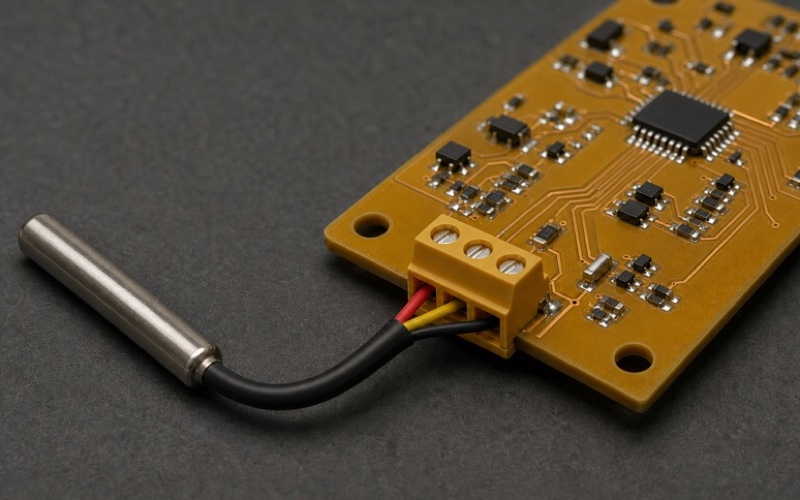
Identify the actual sensor assembly
The DS18B20 datasheet covers the semiconductor in TO-92, SO and micro-SOP forms. A finished stainless probe includes a cable, joints, potting compound and a metal sleeve supplied by another manufacturer or assembler. The IC name alone does not establish immersion depth, ingress rating, cable temperature, pressure resistance, food-contact suitability or response time.
For a probe, obtain an assembly drawing and material declaration in addition to the IC data. Record conductor colors by electrical test rather than assuming every cable uses the same scheme. Check continuity, insulation, seal construction and sensor identity. A counterfeit or substituted digital thermometer can answer simple commands while missing DS18B20 timing, accuracy or ROM behavior.
Choose external or parasite power deliberately
With external power, VDD operates from 3.0 to 5.5 V and DQ remains the open-drain data line. A three-wire probe commonly carries VDD, DQ and ground. This arrangement gives the sensor a defined supply during temperature conversion and lets the master poll conversion status. It also separates energy delivery from data recovery.
In parasite mode, VDD is tied to ground and the device charges an internal reservoir from DQ. The bus then carries both communication and operating energy. A strong pull-up is required during temperature conversion and during a copy from scratchpad to EEPROM. Other bus traffic cannot occur while that strong pull-up holds the line high.
Start with the pull-up, then measure the bus
The datasheet diagrams show 4.7 kilohms as the reference pull-up. That value is a starting point, not a guarantee for every cable and supply. Pull-up resistance and total bus capacitance determine the rising edge. Lower resistance improves rise time but increases low-state sink current; higher resistance reduces sink current but can leave the line below the host's high threshold when it is sampled.
Measure DQ at the farthest sensor with the final cable, connector, protection network, voltage and device count. Check reset recovery, write-one recovery and read slots. Compare the waveform with both the DS18B20 thresholds and the host input threshold. A clean waveform beside the controller can hide a slow or reflected edge at the probe.
Understand the wired open-drain path
The master and every slave communicate by pulling DQ low or releasing it. No participant should drive the line high during normal time slots. This wired arrangement permits multiple devices to share one conductor, but it also means a shorted sensor, reversed cable or active-high GPIO configuration can stop the entire network.
Implement the master pin as open-drain hardware or emulate it by driving low and switching to high impedance. Verify the state through reset and boot so the processor never applies a push-pull high against a responding sensor. A small series resistor and suitable low-capacitance ESD device near the outward connector can limit transients without replacing correct bus design.
Follow reset and presence timing
Every normal transaction begins with initialization. The master pulls DQ low for at least 480 microseconds, then releases it. A DS18B20 waits 15 to 60 microseconds and produces a presence pulse lasting 60 to 240 microseconds. The master must observe that window before sending a ROM command.
Use a timer or a carefully characterized low-level driver rather than an unbounded software delay. Interrupt latency, clock scaling and task switching can move sample points. Capture the reset and presence sequence across temperature and supply limits. A missing presence pulse should be treated as a physical or timing fault, not as a valid temperature sample.
Use the 64-bit ROM identity correctly
Each DS18B20 stores a 64-bit ROM code. The least significant byte is family code 28h, the next 48 bits form a unique serial number, and the most significant byte is a CRC. Search ROM identifies every slave on a multidrop bus. Match ROM then selects one device for a function command.
Store the full ROM value together with physical sensor location. If a probe is replaced, update that mapping under controlled service. Read ROM is valid when exactly one slave is present. Skip ROM can broadcast a conversion to all sensors, but a following Read Scratchpad on a multidrop bus causes several devices to transmit together and corrupt the response.
Schedule conversion time from resolution
The configuration register selects 9, 10, 11 or 12-bit conversion. Maximum conversion time scales accordingly: 93.75 ms, 187.5 ms, 375 ms and 750 ms. Higher resolution gives a smaller numeric step but does not improve the specified absolute accuracy by itself. Select resolution from control-loop needs, noise and update rate.
With external power, the master can issue read slots after Convert T and observe a zero while conversion is active and a one when it is complete. Parasite-powered devices need the strong pull-up for the entire conversion, so that polling method is unavailable during the hold. The host must reserve the proper interval for the configured resolution.
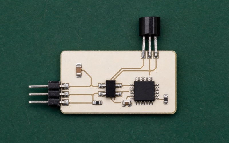
Read all nine scratchpad bytes
The scratchpad contains nine bytes. Bytes 0 and 1 hold the signed temperature value. Bytes 2 and 3 hold high and low alarm thresholds, byte 4 holds configuration, bytes 5 through 7 are reserved, and byte 8 contains the CRC. At 12-bit resolution the temperature uses a sign-extended two's-complement representation with a step of 0.0625 degree Celsius.
Reading the full scratchpad supports a CRC check and confirms configuration. Treat reserved bytes according to the datasheet rather than assigning application meaning. Convert the signed value carefully, especially below zero. Test known positive, zero and negative examples so byte order and sign extension errors appear before field deployment.
Verify the CRC before accepting data
The DS18B20 uses the polynomial x^8 + x^5 + x^4 + 1 for its 8-bit CRC. A CRC protects the ROM identity, and the ninth scratchpad byte protects the first eight scratchpad bytes. The bus master performs the calculation and decides whether to accept or reject a response.
Do not publish a temperature value from a failed CRC. Count failures by sensor and time, then retry under a bounded policy. Repeated errors can indicate cable reflections, inadequate recovery time, weak parasite energy, electromagnetic interference or a damaged connection. A retry that eventually succeeds should remain visible in diagnostic data.
Keep ROM commands and function commands in order
A normal access contains reset and presence, a ROM command, then a device function command and any data exchange. Search ROM and Alarm Search return to initialization after their search cycle. Match ROM addresses one sensor. Skip ROM addresses all devices and is useful for simultaneous conversion when the bus design can power the group.
Convert T starts measurement. Read Scratchpad returns up to nine bytes. Write Scratchpad changes alarm thresholds and resolution in volatile scratchpad fields, while Copy Scratchpad transfers those fields to EEPROM. Parasite-powered Copy Scratchpad requires a strong pull-up within the datasheet timing and for at least the specified write interval.
Design strong pull-up control safely
A strong pull-up is an active low-resistance path to the bus supply. It is enabled after Convert T or Copy Scratchpad when parasite-powered devices need extra current. It must be disabled before normal communication resumes because a slave cannot pull DQ low against an active strong source.
The control circuit needs a known reset state, adequate current capacity and timing tied to the actual command. Verify voltage at the farthest sensor throughout conversion. Consider total simultaneous load when broadcasting Convert T. External power is often simpler when a third conductor is already present, as in a three-wire probe.
Control cable topology and branch length
Long 1-Wire networks behave as transmission structures with distributed capacitance and reflections. A linear trunk with short stubs is easier to manage than a large star. Each branch, connector and protection device adds loading. Cable type and conductor pairing also influence impedance, noise pickup and return-current area.
Document total length, maximum branch length, connector count and sensor count. Test the exact assembled network rather than a single sensor on a short jumper. Analog Devices guidance recommends studying the waveform and adjusting master timing, recovery, pull-up behavior or driver choice when network weight increases.
Allow recovery time for multiple slaves
The minimum recovery time in a simple datasheet slot assumes a limited network. Multiple devices and cable capacitance need more time for the line to recharge and rise. If the next slot starts too quickly, a logical one can be sampled as zero or a parasite-powered device can lose energy.
Measure the rise to a valid high level and set slot timing with margin. A lower passive pull-up, an active pull-up master or a dedicated 1-Wire interface may help, but each changes sink current and timing. Validate read, write, reset and conversion under minimum supply and maximum cable loading.
Place protection at the cable entry
A remote probe cable can carry electrostatic discharge, electrical fast transients and ground differences into the controller. Put the terminal at the board edge with a short path to protection. Select an ESD device whose capacitance does not consume the bus rise-time margin. Route surge current away from the host and pull-up reference.
For harsh environments, review series impedance, shielding, grounding and isolation needs. Protection cannot make an arbitrary cable reliable by itself. Run immunity tests while logging CRC failures, presence loss and resets, then inspect whether the bus returns to a known state after each event.
Separate sensor accuracy from thermal accuracy
The IC accuracy specification applies to the silicon temperature under defined conditions. The measured process can differ because of probe sleeve conduction, cable heat flow, potting, mounting pressure, self-heating, airflow and thermal gradients. A steel sleeve immersed only at its tip may conduct heat from the surrounding structure.
Compare the complete probe against a traceable reference at several stable temperatures. Allow enough soak time and record immersion depth, medium, orientation and cable routing. Calibration can characterize an assembly, but it should not hide unstable bus communication or unidentified sensor hardware.
Build fault handling into the host
Track presence, ROM identity, conversion state, CRC result, timeout and range separately. A missing sensor is different from a valid low temperature. Retain the last good value with an age indicator only when the application permits it. Control systems should enter a defined state when data becomes stale or invalid.
On a multidrop bus, isolate repeated errors to the physical location mapped to each ROM code. A short circuit can affect every node, while one bad branch may create intermittent reflections. Service diagnostics should display the identity and failure type rather than a generic sensor error.
Complete the DS18B20 bus review
Before release, confirm the genuine sensor identity, package or probe construction, power mode, supply range, DQ pull-up, open-drain behavior, reset timing, ROM discovery and physical-location mapping. Verify resolution, worst-case conversion interval, scratchpad decoding and CRC handling.
Review cable length, branch topology, recovery time, strong pull-up timing, protection capacitance, connector orientation, thermal installation and fault response. Capture waveforms at the farthest node under maximum loading and temperature. A reliable temperature channel results from the bus, power, protocol and mechanical measurement path working together.
Related information
- 2026.07.17 LM35 as an Analog Voltage Temperature Sensor
- 2026.07.17 TMP102 for Low Cost Board Temperature
- 2026.07.17 TMP117 for High Accuracy Digital Temperature
- 2026.07.17 VS1011E as an Integrated MP3 Audio Decoder


