 Free Shipping Over$200

- Products
- Marking
- Alternative

TMP102 for Low Cost Board Temperature
TMP102 for Low Cost Board Temperature
TMP102 is a compact digital sensor for monitoring the temperature of the PCB region where it is mounted. The official TI product page lists an active device with a two-wire I2C and SMBus interface, a programmable alert, four address choices and a 1.6 mm by 1.6 mm SOT563 package. It is a practical choice when a controller needs a direct board-temperature value without an analog thermistor network and ADC channel.
The part should be selected against its guaranteed limits rather than the smallest number in a typical curve. The current TMP102 data sheet specifies maximum error of 2.0°C from -25°C to 85°C and 3.0°C from -40°C to 125°C. Its 12-bit temperature result has 0.0625°C resolution. That code step provides smooth reporting and threshold control, but it is much smaller than the guaranteed absolute error.
Board placement defines the meaning of the reading. A TMP102 beside an MCU measures a thermal blend dominated by local copper, package leads, airflow and nearby dissipation. It does not remotely sense the hottest junction inside the processor. The design has to name the board location being monitored and create a sensible thermal path from that region to the sensor.
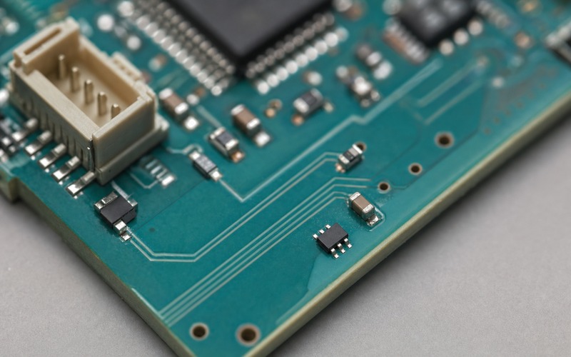
Define what board temperature means
Board temperature can support fan control, performance reduction, battery charging limits, enclosure diagnostics or an early warning that cooling has degraded. Each function can require a different location. Monitoring the MCU neighborhood is different from monitoring the power entry, battery connector or ambient air inside the enclosure.
Write the functional target in physical terms, such as the top-layer copper beside the main controller, rather than using a vague label such as system temperature. State the permitted error, threshold, response time and operating range at that location. This makes placement and validation testable.
If the real requirement is processor junction temperature, use an internal sensor or a supported remote-diode channel where available. A local TMP102 can still monitor the surrounding PCB, but software must not present that value as a direct junction measurement.
Apply the guaranteed accuracy range
TMP102 operates from -40°C to 125°C. The maximum accuracy limit is 2.0°C over -25°C to 85°C and 3.0°C over the full rated range. Set a protective threshold with those limits, thermal offset and system response delay included. A threshold at the exact material limit leaves no margin for measurement uncertainty.
Resolution is 0.0625°C per code. Use that granularity for filtering, trend detection and hysteresis, but do not claim hundredths of a degree as absolute system accuracy. Display formatting should match the uncertainty that the product can support.
TI states that production testing is traceable to NIST through equipment verified with ISO/IEC 17025 accredited calibrations. That supports the device test chain. Product-level verification is still needed because local heat flow and enclosure conditions can shift the board reading.
Place the SOT563 close to the intended board region
TI explains that heat reaches the TMP102 die mainly through the metal package leads, with another path through the molded body. The sensor should therefore sit close to the region it monitors, with copper that encourages thermal equilibrium between that region and the leads.
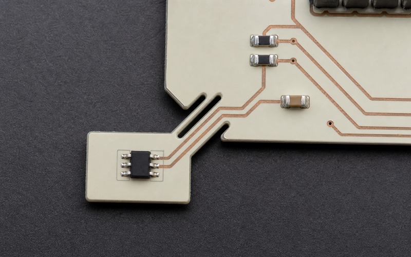
For MCU-area monitoring, use a short copper path or a shared ground region between the controller neighborhood and TMP102. Avoid a routed thermal moat between them because that would slow and weaken the intended coupling. The sensor does not need to touch the MCU package to follow board temperature.
Keep the device away from a regulator, switching transistor, power resistor or indicator lamp unless that part is the target. A few millimeters can matter when a small power device creates a steep local gradient. Place the sensor so its strongest copper path leads toward the intended region rather than the unrelated hot component.
Use copper to couple, but avoid averaging the whole board
A solid ground connection can spread heat effectively between a component and a nearby local sensor. The TI surface-mount temperature layout report recommends a conductive path when the objective is component temperature and physical isolation when the objective is ambient air. TMP102 board monitoring belongs to the first case.
Do not extend the coupling copper across the entire appliance board. A large plane can combine the regulator, connector and controller temperatures into one slow average. Keep the thermal relationship local enough that a change at the intended region appears clearly.
Board stack-up also matters. Internal planes and thermal vias can bring heat from the opposite side. Inspect all layers and the assembled enclosure before assuming that top-layer distance alone isolates the sensor from the power section.
Separate the regulator heat path
A compact consumer or appliance controller often places the MCU, regulator and sensor within a small area. Put the TMP102 near the MCU-side ground region while breaking direct wide copper toward the regulator. Maintain electrical return integrity, but avoid using the sensor pad area as part of the regulator's heat spreader.
Place the regulator downstream of airflow where possible, or add board spacing so warm air from the regulator does not cross the sensor first. Convection can override the copper layout in a small enclosure. A practical arrangement puts the sensor between the controller and a quiet board edge, with the regulator kept farther away.
Verify the gradient with thermocouples or a calibrated surface probe at the sensor, MCU neighborhood and regulator. An infrared image can help locate heat flow, but emissivity and reflections must be controlled before using it as quantitative evidence.
Connect the supply and pullups correctly
TMP102 operates from 1.4 V to 3.6 V and is optimized for 3.3 V operation. TI recommends a 0.01 µF supply bypass capacitor placed close to the supply pin. Keep the loop to ground short and avoid routing the sensor supply beside a noisy switching node.
SCL, SDA and ALERT use pullup resistors. TI shows 5 kΩ as the recommended starting value and limits low-level current on those pins to 3 mA. Calculate the final value from bus capacitance, required rise time, controller limits and bus voltage.
The I2C lines may be pulled to a voltage equal to or higher than the TMP102 supply within the device limits stated in the data sheet. Check every controller and bus participant before using that capability. Do not infer whole-bus compatibility from the sensor pins alone.
Select one of four bus addresses
Connect ADD0 to ground, the supply, SDA or SCL to select 0x48, 0x49, 0x4A or 0x4B. This allows four TMP102 devices on one bus for several board zones. Record the strap in the schematic and make it visible enough for manufacturing inspection.
An address strap tied to a signal line must be routed as an intentional local connection. Avoid a long branch that adds capacitance or noise pickup. Firmware should scan only approved addresses and report a missing sensor explicitly rather than silently substituting another channel.
When several devices share the bus, label values by physical location. A raw address is not an adequate service description. Store a board-zone mapping in firmware and in test documentation.
Decode the signed temperature result safely
In normal mode, the temperature register contains a 12-bit signed two's-complement value across two bytes. The four least-significant bits of the second byte are unused. Combine the bytes, shift the result to align the 12-bit value, sign-extend it, and multiply by 0.0625°C.
Test the routine with positive and negative values, including the transition through zero. A common failure treats the data as unsigned or forgets the four-bit shift, producing plausible values at room temperature and incorrect results below zero.
After power-up or reset, the temperature register reads 0°C until the first conversion finishes. Firmware should wait for the conversion interval or verify conversion readiness before using that value in control logic.
Understand extended mode without exceeding ratings
Extended mode changes the temperature and limit registers from 12-bit to 13-bit data so the numeric format can represent temperatures above 128°C. It does not raise the TMP102 rated operating maximum of 125°C. Keep system operation within the published range.
Firmware must use the correct shift and sign extension for the selected format. Store the mode with configuration data and add unit tests for both forms if software supports both. A mode mismatch can double the interpreted value or move status bits into the measurement.
Most board-temperature applications can remain in normal mode. Enable extended mode only when the system has a documented reason and the conversion code has been reviewed against the register format.
Choose conversion rate from response and power needs
Continuous mode supports 0.25, 1, 4 or 8 conversions per second, with 4 Hz as the reset default. A conversion typically takes about 10 ms; the device then powers down internally until the next selected interval. Faster reporting is useful for a rapid local event, while slower rates reduce average activity.
The thermal response of the board assembly is usually slower than the ADC conversion. TI measured a 0.8 second time constant in an oil-bath step using its stated small two-layer test board, but the result depends strongly on PCB construction. A large appliance board and enclosure need their own measurement.
Choose the conversion rate after observing the assembled response. Reading at 8 Hz does not make a thermally sluggish placement respond eight times faster. It can provide more samples of the same delayed physical temperature.
Use shutdown and one-shot modes for low duty cycle systems
The data sheet lists 7.5 µA maximum active quiescent current and 0.35 µA maximum shutdown current. In shutdown, the serial interface remains available. Writing the one-shot bit starts one conversion, after which the device returns to shutdown.
A typical one-shot conversion takes 10 ms. A battery device that checks board temperature occasionally can wake the sensor, wait for completion, read the result and leave it shut down. Coordinate the measurement with major load events if the purpose is to observe their thermal effect.
Power mode should be explicit after reset. Verify configuration readback before relying on current estimates. Bus traffic also consumes power, so measure the complete system current rather than multiplying a single data-sheet number by the sample rate.
Configure ALERT for useful hysteresis
TLOW and THIGH define the alert thresholds. In comparator mode, ALERT activates at or above THIGH and remains active until temperature falls below TLOW. This creates programmable hysteresis for fan control or protection.
In interrupt mode, the alert is cleared when the controller reads the temperature register. Choose the mode to match firmware behavior. A level-sensitive safety response often differs from an event that software acknowledges and logs.
ALERT polarity is configurable. Confirm the external pullup voltage, controller input state during reset and the safe state if firmware stops responding. Exercise both threshold directions during board test.
Use consecutive-fault counting to reject brief disturbances
The consecutive-fault setting can require 1, 2, 4 or 6 out-of-limit measurements before asserting ALERT. This helps prevent a brief disturbance from triggering a response. The real delay equals the selected count multiplied by the conversion interval, plus thermal and software latency.
Do not set a long consecutive count for a protection function without calculating that delay. At 0.25 Hz, six consecutive measurements can add a substantial wait. A comfort-control function may accept that filtering, while a fast hardware risk may require another protection path.
Test with temperature ramps near the threshold and with injected bus activity. Confirm that the chosen combination of rate, fault count, comparator mode and hysteresis behaves predictably.
Filter trends in firmware without hiding faults
A moving average can smooth display noise, but protection logic should use a clearly defined filtered or unfiltered channel. Long filters can conceal a rapid board-temperature rise. Keep raw samples available for diagnostics.
Use range checks and rate-of-change checks to detect open communication paths, reset values and impossible jumps. A valid I2C transaction is not proof that the reported channel matches the correct physical sensor.
Store threshold crossings with raw temperature, address, mode and time. This makes field data useful when comparing enclosure, cooling and board revisions.
Validate the physical location in the final enclosure
Run the product through normal, high-load and fault-relevant operating modes. Measure the TMP102 location, the target board region and unrelated heat sources. Repeat with the enclosure closed because airflow and radiation can change the gradient.
Test several units and board lots. Copper thickness, component dissipation, thermal interface materials and mounting pressure can shift the local relationship. Confirm both steady-state difference and response during power transitions.
Use the measured offset when setting control thresholds. If the offset changes greatly with load, improve placement or thermal routing instead of applying one constant software correction.
Review substitutes by function and layout
Compare alternate digital sensors by guaranteed accuracy over the required range, supply, package, pinout, address options, conversion modes, alert behavior and software register format. A smaller or more accurate device may still require a new footprint and different thermal response.
Do not assume that an LM75-compatible register description makes a part electrically or mechanically interchangeable. Check default configuration, threshold format, bus timeout behavior, power-up result and ALERT clearing.
Keep the exact TMP102 package option with the approved land pattern. The SOT563 geometry and lead-based thermal path are part of the qualified measurement, not a purchasing detail that can be changed independently.
Finish with a board-temperature checklist
Confirm the physical board zone, required range, maximum error, threshold margin and response time. Place TMP102 near the target region with useful local copper, no isolation moat, and no direct wide thermal path to the regulator. Check every board layer and enclosure airflow.
Verify the 1.4 V to 3.6 V supply, 0.01 µF bypass, pullups, ADD0 strap, bus rise time and ALERT interface. Test signed conversion, first-result handling, normal or extended mode, conversion rate, shutdown, one-shot operation, threshold mode and fault count.
Finally, compare the sensor result with calibrated probes in the assembled product across the intended loads and temperatures. TMP102 then becomes a useful low-cost board monitor with a defined physical meaning, rather than a digital number whose relationship to the hardware is unknown.
Related information
- 2026.07.17 LM35 as an Analog Voltage Temperature Sensor
- 2026.07.17 TMP117 for High Accuracy Digital Temperature
- 2026.07.17 DS18B20 on a One Wire Temperature Bus
- 2026.07.17 VS1011E as an Integrated MP3 Audio Decoder


