 Free Shipping Over$200

- Products
- Marking
- Alternative

Turning a Weak Sensor Output Into a Clean Digital Reading
A weak sensor output does not become useful because it reaches an ADC pin. It becomes useful only after the board has protected the part of the signal that carries meaning and thrown away the part that only looks like meaning. A millivolt from a bridge, a few microvolts from a thermocouple, a slow electrode voltage from chemistry, a pulse train from a rotating shaft: each one asks the front end to keep a small truth alive while power rails, ground currents, radio noise and temperature drift all try to write over it.
The hard choice is rarely between analog and digital. It is where to spend the analog care before the number exists. Put gain too early and the amplifier may saturate on offset. Put it too late and the converter spends its range measuring empty headroom. Buy more bits than the sensor can justify and the lower codes only resolve noise. Buy too few and a clean signal gets rounded into steps that firmware cannot smooth back into shape.
Resolution starts at the sensor
Choosing ADC resolution by the sensor, not the spec sheet, is the first rule because resolution is not a badge printed on the converter. A sixteen-bit ADC divides its reference into many codes, but those codes only mean something if the sensor span, the front-end noise and the reference stability leave real information between them. A load cell that moves ten millivolts across full load can use far more converter help than a potentiometer swinging rail to rail. A temperature sensor that drifts with board heat may not repay a jump from twelve bits to twenty-four. The right question is not how many bits the ADC has. It is how many usable counts remain across the sensor span after gain, offset, noise and calibration have taken their share.
That is why the common small converters sit in such different jobs. The ADS1115 is a common 16 bit I²C ADC, and it fits the board that needs a modest number of slow analog channels without building a precision acquisition system. Its internal programmable gain lets a small sensor span occupy more of the code range, and its I²C interface makes it easy to add to a microcontroller design that has run out of ADC pins. The trade is speed and channel timing. It samples slowly enough for temperature, pressure, battery voltage and other steady quantities, not for vibration, audio or sharp transients, and the I²C bus means the converter is part of a shared digital schedule. It is useful because it is tidy, not because sixteen bits by themselves make a weak signal clean.
The ADS1256 does 24 bit high precision acquisition in a different class, where the design wants slow, low-noise, multi-channel measurement and is willing to treat the converter as a precision part instead of a helper IC. Delta-sigma architecture buys resolution by oversampling and digital filtering, so the quiet reading arrives with latency and a data rate chosen from a set of compromises. The input multiplexer, reference routing and digital filter settings become part of the measurement plan. A part like this belongs near bridge sensors, weigh scales, lab instruments and slow process signals, where the value changes gently enough that trading time for code depth makes sense. It also exposes the weakness of a casual layout: a twenty-four-bit converter will report ground noise, reference noise and thermal gradients with the same sincerity that it reports the sensor.
The MCP3008 adds eight 10 bit channels to an MCU, which sounds crude beside a precision delta-sigma converter and is exactly why it survives. It is the part for knobs, battery rails, light levels and low-cost analog housekeeping, where a quick SPI transaction and enough channels matter more than microvolt work. Ten bits across a 3.3 volt reference put each code in the millivolt range, fine for a panel control and wasteful for a bridge output unless the bridge already has gain. Its value is that it keeps simple analog inputs simple: one package, eight channels, no claim that it can rescue a signal whose span was never lifted into view.
The AD7606 is for multichannel simultaneous sampling, the case a multiplexed ADC cannot cover cleanly. When several voltages describe one event, such as phase currents, vibration axes or power-line waveforms, reading them one after another creates time skew that looks like signal error. A simultaneous sampler freezes several channels at the same instant, then shifts the results out afterward. The input ranges are sized for industrial signals rather than bare sensor nodes, so it often sits after scaling and protection, and its channel count changes the layout problem from one delicate trace to a bundle of matched ones. The point is timing: if the channels must be compared against each other at one moment, converter resolution is not enough. Sampling instant becomes a specification.
When the front end becomes the sensor
The AD8232 is a single lead ECG front end, and it shows why some measurements do not start at the ADC at all. The useful ECG signal is small, slow and riding on a body that picks up mains interference, electrode offset and motion artifact. The chip puts the amplifier and filters close to that problem so the output already sits in a range a microcontroller can sample. It is not a generic op amp plus converter recipe; it is a front end shaped around a known source impedance, electrode behavior and band of interest. That is the lesson for every sensor chain around it. When the source is hard, the conditioning is part of the sensor, not an accessory after the fact.
Gain is where the signal earns its bits
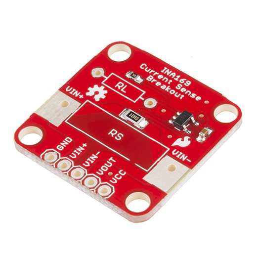
The amplifier's first job is not to make the signal large. It is to make the right part of the signal large. A bridge sensor gives a differential voltage while both wires ride on an excitation common mode. A thermocouple gives a voltage that changes with the junction while its leads collect noise from the world. A pH or chemical electrode can have high source impedance, making bias current and leakage part of the reading. A shunt can sit near ground or near a high rail. Each source has a different enemy, so the front end starts by choosing what to reject: common-mode voltage, input offset, drift, bias current, wideband noise, mains pickup, or a rail transient that would otherwise slam the amplifier into a stop.
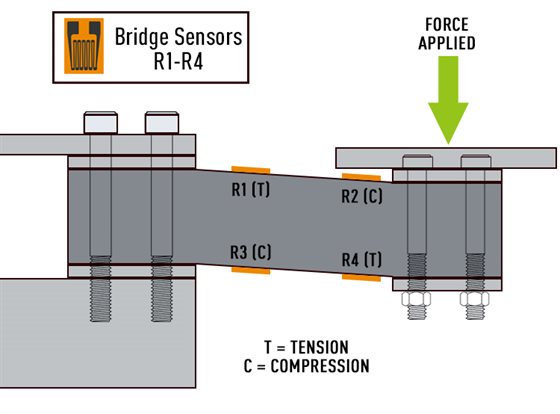
The AD620 is an instrumentation amplifier for a bridge sensor, the familiar answer when a small differential signal must be lifted while the shared voltage on both inputs is ignored. A single external resistor sets the gain, which keeps the design readable and puts the gain-setting error in one place. It fits load cells, pressure bridges and other sensors whose output is a few millivolts per volt of excitation, provided the input common-mode range, output swing and supply rails all leave enough room. The trap is assuming a bridge amplifier only needs a large gain number. At high gain, offset and drift are multiplied with the signal, and the output can run into a rail before the real span has even started. Bridge work is a headroom problem as much as an accuracy problem.
The INA128 handles low noise instrumentation amplification in the same family, with the quiet front-end behavior a precision bridge or biomedical channel asks for. Its value is not one heroic headline spec but the combination of input noise, bias current, gain accuracy, common-mode rejection and temperature drift staying tame together. That balance matters because the sensor does not give the amplifier a clean classroom waveform. It gives a small difference riding on a changing common-mode voltage, and the amplifier has to keep the difference while ignoring the ride. A cheaper stage can pass the bench test at one temperature, then move its zero enough in the enclosure to make the calibration look like it failed.
The OPA333 is for zero drift amplification of a weak signal, a case where slow accuracy matters more than wide speed. Zero-drift amplifiers use internal correction to keep offset from wandering, which suits strain, temperature, bridge and chemical signals whose value changes slowly but whose baseline must not creep away. They are not magic silence. The correction method can leave ripple or switching artifacts that a design has to filter, and the bandwidth is not meant for fast waveform capture. A zero-drift op amp is the right answer when the error to fight is slow offset movement, not when the signal itself needs wide bandwidth.
The AD7740YRMZ sits in a voltage to frequency front end, a less fashionable route that still solves a stubborn distance problem. A voltage that travels down a long cable arrives as a vulnerable analog level. A frequency can cross the same distance as edges, and the receiver can count time rather than measure amplitude. That makes voltage-to-frequency conversion attractive when isolation, cable loss or noisy ground references would damage a direct voltage reading. It is not free: linearity, temperature drift, input range and count time all move into the error budget. Yet for some slow sensors, a frequency is a cleaner messenger than a voltage.
Frequency is another way to move an analog value
The LM331 turns an analog value into a frequency output, and its age is part of why it remains easy to understand. The input voltage controls a pulse rate, so the receiving system measures frequency with a timer, a counter or an isolated digital input. This can move an analog reading across an optocoupler or a cable with less pain than preserving a low-level voltage. The price is time. A frequency measurement needs a gate interval long enough to count edges accurately, so resolution improves as the reading gets slower. It suits slow process variables, old industrial interfaces and isolated sensor paths, not a control loop asking for a fresh value every few microseconds.
The LM2907 converts a frequency signal back to a voltage, the opposite side of the same bargain. A tachometer, fan sensor, wheel pickup or flow rotor may already produce pulses, and a frequency-to-voltage converter turns those pulses into a level that a meter, comparator or ADC can read. The output smooths the pulse train, which means it also hides individual pulse timing. That is useful when the system wants a steady speed signal and harmful when the firmware needs to see jitter, missing teeth or fast acceleration. Again the front end decides what form of information survives: a clean average voltage, or the raw edge timing.
Edges are numbers too.
The swap that fails although the pins line up
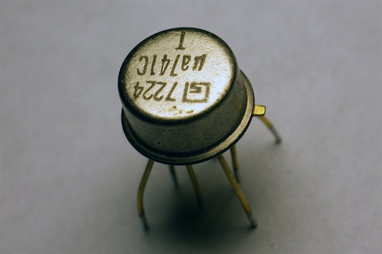
A pin compatible ADC swap can still fail in the field because the pinout is only the outside of the part. Two converters can share a package and bus while disagreeing on input sampling current, reference behavior, digital filter delay, channel sequencing, startup time, input protection leakage, clocking, alert polarity or how they report overrange. A board that worked with one part may have source impedance too high for the next part's sampling capacitor, so the input never settles before conversion. Firmware that assumed one conversion latency may read stale data from a delta-sigma replacement. A reference pin that was quiet enough for the original may feed more noise into a higher resolution substitute. The failure appears in production because the bench stimulus was gentle, the cable was short, the temperature was kind and the firmware exercised only the happy path. A real substitute has to match the electrical contract, timing contract and firmware contract as well as the copper footprint.
The same warning applies to amplifiers. A drop-in op amp can oscillate with the old input filter, drive the ADC sample capacitor poorly, lose output swing near the rail, or leak enough input bias current through a large sensor resistance to move the reading. A component replacement is a measurement-chain replacement unless the chain proves otherwise.
The single-channel and lab ends of the same chain
The MCP3421 is a single channel 18 bit measurement part, the small end of precision acquisition. It suits a board that needs one careful analog number, not a rack of channels: a pressure reading, a bridge after gain, a slow voltage monitor, a calibration point. Its internal reference and programmable gain reduce the outside circuit, while I²C keeps the wiring small. The appeal is discipline. With one input, the designer can route, filter and guard the signal path instead of treating analog as one more pin bank on the microcontroller.
The AD5522JSVUZ belongs in sensor and device characterization, where the job is to read a sensor, force conditions onto it and watch how it responds. A device-under-test front end may need to source current, clamp voltage, measure leakage or step through operating points under software control. That is a different relationship with the analog world. The circuit becomes an instrument rather than a plain input path. It is useful during characterization because it finds the real curves that later turn into a product's simpler front end: the bridge excitation that gives enough span, the leakage that ruins a high-impedance node, the settling time after a range change, the corner where a protection device starts to distort the reading.
Those two parts, a small single-channel ADC and a programmable measurement unit, bracket the same idea. A product front end is the frozen answer to questions a lab front end first asks. How wide is the signal span? How fast does it move? What common-mode voltage rides with it? What happens when the cable is unplugged, shorted, wet or hot? Where does the zero go after an hour? Which error term dominates once the box is closed? The article one level up called this a signal chain, but here the chain is narrower: gain, conversion, timing and substitution all serve the same purpose, which is to deliver a number that still means what the sensor meant.
The clean digital reading is the last thing the chain produces and the first thing firmware trusts. That trust is earned upstream. Pick the ADC by the sensor span, not by the bit count alone. Put gain where it enlarges signal before noise, not where it hides headroom. Use frequency when a voltage cannot travel cleanly. Treat pin-compatible swaps as new measurements until the timing and analog behavior prove they are not. A weak sensor output can become a clean number, but only when the board respects every small analog fact before it asks software to believe the result.






