Whether Dev Board Performance Carries to Production
A development board can make a processor look faster than the product board that later carries the same part. The difference often comes from conditions around the part: memory distance, power rail stiffness, thermal path, camera feed, clocks, firmware build, enclosure and the way the benchmark is triggered.
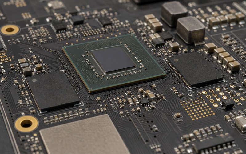
That means the question is not whether the silicon is fast enough in the abstract. The useful question is narrower: which part of the development-board result can survive the move into the production layout, and which part has to be proven again on the real board?
Treat the early result as a measured condition, not a promise. Each performance claim should be tied to board revision, firmware, input data, ambient condition, rail behavior, heat path and I/O state. Without those anchors, a number taken from a dev board can become a weak release argument.
Contents
- Name the Benchmark Before Trusting It
- Compare Compute and Memory Conditions
- Check Power Rail Behavior Under the Workload
- Thermal Headroom Changes Sustained Speed
- Watch the I/O Path That Feeds the Workload
- Keep Firmware, Clocks and Build Settings Comparable
- Build a Product-Board Test Method
- Decide What Can Transfer
- Performance Transfer Checklist
Name the Benchmark Before Trusting It
A performance number needs a job name. Frames per second, inference time, wake-to-decision time, sensor-to-cloud latency and sustained throughput are different measures. A dev board may score well on one and fail another once the workload is placed in a product with enclosure heat, shared buses and real input data.
Start by naming the workload. Define the model, tensor shape, image size, batch setting, pre-processing path, memory format, precision, driver version and firmware build. If the test includes a camera, name the frame rate, exposure behavior and input path. If it includes a radio or wired link, name the traffic level and peer device.
Then define the timing window. A cold first run is not the same as a warm steady run. A one-second burst is not the same as ten minutes inside a closed housing. The development board may have a heatsink, open air and a lab supply, while the production board has a smaller copper area and a power budget shared with other loads.
Record what was measured and how. Was the time read from firmware logs, GPIO toggles, host software, camera timestamps or user-visible response? Each method can include or exclude a different piece of the path. Production release work needs the same measurement boundary used on both boards.
Compare Compute and Memory Conditions
Many edge AI workloads are limited by memory movement rather than the arithmetic block alone. A development board may use a wider memory bus, a faster memory grade, a different layout, a larger cache setting or fewer devices sharing the memory channel. When the production board changes any of those details, the same model can run slower.
Check the memory topology before accepting a benchmark transfer. Look at bus width, memory type, speed grade, routing length, termination, power rail, boot configuration and firmware memory settings. A small layout change can alter signal margin. A lower-cost memory substitution can change access timing or thermal behavior.
Pre-processing also matters. If the dev board receives already resized images from a host, while the product board must read a sensor, crop, rotate, color-convert and normalize the frame, the compute number is missing part of the product workload. The benchmark should include the path the customer will use.
Shared resources can hide another gap. Storage writes, network traffic, display output, logging and sensor polling can compete for memory and bus time. A bare benchmark loop can look fine until the rest of the product firmware is active.
Check Power Rail Behavior Under the Workload
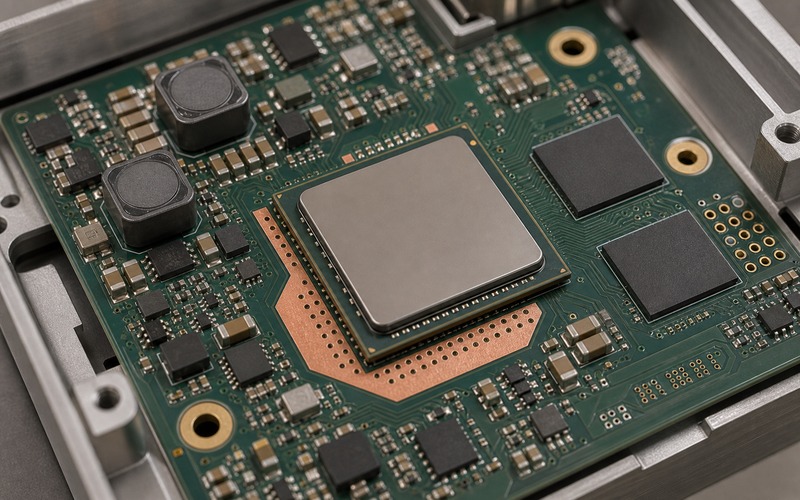
Compute performance depends on the rail that feeds the processor, memory and accelerator. A development board often has a generous regulator, thick copper and a lab supply. A production board may use a smaller converter, longer power path and a shared input stage. Load steps can create droop, ripple or current limit events that change clock behavior.
Measure the rail during the workload, with idle treated as one reference point rather than the whole proof. Check startup, model load, first inference, repeated inference, camera activity, storage access and communication bursts. A short current spike can trigger a protection limit or force firmware into a lower clock state. A rail that reads correct on a slow meter can still dip during the event that sets performance.
Regulator selection, compensation, inductor current, capacitor bias loss and layout loop area all affect the result. A part that met the schematic current target may still run hot or respond slowly in the product placement. If a rail feeds both compute and I/O, the I/O burst can disturb the compute block.
Power measurement should use the product input path. USB power on a dev board can mask cable drop and input protection loss. A product board fed through its final connector, fuse, reverse-protection part, converter and copper path tells a better story about real speed.
Thermal Headroom Changes Sustained Speed
A development board may sit flat on a bench with a large heatsink and air around it. A product board may sit behind plastic, near a battery, under a lid or against a metal bracket. The first few runs can match the dev board, then the product slows as junction temperature climbs.
Separate peak speed from sustained speed. Peak speed answers whether the chip can run a short task. Sustained speed answers whether the product can keep that speed through the required operating window. The two numbers can differ sharply when the heat path changes.
Thermal testing should include input voltage, ambient, enclosure, mounting orientation and surrounding loads. A power regulator near the processor can heat the board from one side. Memory packages can warm the processor area. A camera or radio module may raise local temperature even if it does not draw much current.
The release record should state the clock limit, temperature observation point and throttle behavior. If the production board uses a different heatsink, thermal pad, copper area or enclosure contact from the dev board, sustained performance needs fresh proof.
Watch the I/O Path That Feeds the Workload
A model does not run on a bare number. It waits for data. Camera link, sensor bus, storage, Ethernet, USB, PCIe, MIPI, SPI and I2C each can become the real limiter once the design moves from a flexible dev setup to a compact product board.
Check the data path at product settings. A camera connected through a short dev ribbon may work at a margin that the final flex length cannot hold. A storage device on the dev board may load model data faster than the production memory part. A network test through a desktop host may skip security, buffering or retry behavior used by the shipped firmware.
Connector direction and cable length are mechanical details that can affect signal quality. A production board that bends a flex cable tightly, runs a high-speed lane near a noisy regulator or changes the ground return can reduce link margin. The performance symptom may look like compute slowdown even when the processor is waiting for data.
Instrument the wait time. Split capture, pre-processing, model execution, post-processing, output and communication into separate timing markers. That makes the production difference visible instead of collapsing it into one final number.
Keep Firmware, Clocks and Build Settings Comparable
Firmware changes can create performance differences larger than the board change. Compiler options, cache setup, memory allocation, DMA use, driver version, clock tree, power mode and logging level all affect timing. A dev board run done with debug settings can be hard to compare with a production release build.
Lock the clock plan. Processor clock, memory clock, bus clock, camera clock and accelerator clock should be stated for both boards. If the product board uses a different crystal, PLL setting or spread-spectrum choice, the timing path can change. Clock stability can also affect camera links, audio paths and network timing.
Keep the software path honest. If the production firmware adds watchdog service, encrypted storage, security checks, file system work or telemetry, include those costs when they exist during normal use. A benchmark that disables product services can help isolate the processor, but it does not answer the shipped-product question.
Version control the test. Board revision, firmware commit, model file, configuration file and test input set should be named together. That makes a later slowdown traceable to a board change, firmware change or workload change rather than a vague claim that the dev board was faster.
Build a Product-Board Test Method
The product-board test should be boring and repeatable. Use the final input path, final power entry, production memory option, intended cooling method and an enclosure state that matches the release claim. If the product will run closed, at least one performance test should run closed.
Use timing points inside firmware and external confirmation where useful. GPIO markers, event logs and host timestamps can all help when the boundary is clear. The key is consistency. The same start and stop events should be used when comparing dev board, pilot board and later build.
Test around the corners that matter: low input voltage, high ambient, warm restart, full I/O load, storage activity, radio or network traffic and the longest run window needed by the use case. Do not let a clean-room benchmark replace the product condition.
The output should be a small table with the conditions beside the numbers. A performance value without board state, input data, temperature and firmware is easy to misread. A condition-backed value can guide hardware, firmware and sourcing decisions.
Decide What Can Transfer
Some evidence does transfer. The development board can prove that the selected silicon supports the model, that the toolchain can build the workload and that the first performance target is plausible. It can also expose memory size, driver and interface needs before the product PCB is ready.
What does not transfer cleanly is margin. Power droop margin, thermal margin, I/O signal margin, memory timing margin and mechanical service margin belong to the production board. Those margins need measurement after the layout, enclosure and BOM are set.
Use a simple release decision. If the product board repeats the named workload within the accepted range under defined product conditions, the dev-board performance has carried far enough. If it misses, the timing markers should point to compute, memory, power, heat, I/O or firmware rather than forcing a blind board spin.
Performance Transfer Checklist
Before release, compare workload, input data, timing boundary, processor clock, memory setting, power rails, thermal path, I/O feed, firmware build, enclosure state and test duration between development board and product board.
The performance claim is ready to use when the product board has run the required workload through the final power, memory, cooling and I/O paths, with repeatable timing and no hidden bench-only assumptions.