 Free Shipping Over$200

- Products
- Marking
- Alternative

Capturing Sound and Monitoring Vibration on a Device
A microphone and a vibration sensor are the same instrument pointed at two different materials. One reads the pressure wave a sound makes in air, the other reads the acceleration a machine makes in metal, and both hand back a stream of numbers that stands for mechanical motion. The physics underneath is one physics. What changes is the medium, the frequencies that matter, and the units the datasheet prints on the front page.
That shared root is the reason to treat them together, because the selection questions rhyme. A microphone is judged by the quietest sound it can resolve and the loudest it can take without clipping, the gap between those two being its dynamic range. A vibration sensor is judged by the same gap in different clothing, its noise floor against its full-scale acceleration, and by the bandwidth that decides which mechanical faults it can even see. Pick by the span the application needs, the band it lives in, and the interface that carries the result, and the part falls out of the requirements rather than the marketing.
Choosing a digital MEMS microphone
The first fork is the interface, and it splits the four parts into two camps before any other spec matters. A PDM microphone streams a one-bit signal at a few megahertz, the analog waveform encoded as the density of ones in that fast stream, and the host has to run a decimation filter to turn it back into ordinary samples, which is cheap on pins and demanding on the processor. An I2S microphone does that conversion on board and clocks out finished multi-bit samples on a standard audio bus, so two of them share one bus as a stereo pair with no host arithmetic at all. The choice ripples through the whole design: PDM suits a tiny part feeding a codec built to decode it, I2S suits a microcontroller that wants audio it can use straight away. PDM also lets the host throttle the clock to trade bandwidth for power, a lever I2S does not offer, while I2S spares the processor the steady decimation load PDM imposes on every sample, so the camp decides not just the wiring but where the audio workload lands.
The ICS-43434 is a high signal-to-noise digital MEMS microphone with an I2S output, and its number is the signal-to-noise ratio of around 65 decibels that lets it resolve a quiet room where a lesser part hears only its own hiss. Signal-to-noise is the spec that decides how faint a sound survives the trip into digits, and a high one is what separates a microphone for far-field voice pickup, where the talker is across the room, from one that only works with a mouth against the grille. It clocks finished samples onto the I2S bus at up to a twenty-four-bit word, pairs into a stereo array for the beam-forming that locates a speaker, and asks nothing of the host but a clock. Its response stays flat across the speech band, and its low self-noise holds the floor down where a far-field array sums several units and adds their noise along with the signal, which is why it shows up in smart speakers and voice remotes by the million.
The INMP441 is an I2S output digital microphone and it is the part people reach for first when they want audio into a microcontroller with no analog stage at all. It carries the same on-board conversion, outputs the standard bus, and selects left or right channel by a pin so a stereo pair drops onto one set of wires. It runs a high-pass filter on chip to shed DC and low rumble, holds a signal-to-noise ratio around 61 decibels and a flat response through the voice band, and draws a current small enough for a battery toy. Its specifications sit a notch below the highest tier, and that is the point of it: it is the dependable, documented, widely cloned starting microphone, the one every example project and dev board assumes, and the one a design uses until a requirement appears that it cannot meet.
The IM69D130 does high dynamic range microphone capture, and dynamic range is its whole reason to exist. It pairs a low noise floor with a high acoustic overload point, the sound pressure where the signal starts to clip, near 130 decibels, so the same part resolves a whisper and survives a sound that would flatten an ordinary microphone. The span between its floor and that ceiling reaches about 105 decibels, and its phase stays flat low into the bass, which counts when several units feed a beam-former that adds their outputs and punishes any phase the units fail to share. That span is what a design needs when the sound is unpredictable: a body camera that records both a quiet conversation and a gunshot, a drone over a noisy rotor, an industrial monitor near machinery, anywhere the loud and the soft arrive through the same grille and both have to come back clean and undistorted.
The MP34DT05 is a compact PDM microphone, and it earns its place on size and integration where the host already has a PDM input waiting. It is small enough to tuck into the bezel of a laptop or the rim of a wearable, streams its one-bit signal to a codec or microcontroller built to decimate it, and trades the host-side filtering work for a footprint the I2S parts cannot match. Its clock runs from the low hundreds of kilohertz for a sleep-mode listen up to a few megahertz for full bandwidth, so the same part trades resolution against power on command, and its omnidirectional pickup takes sound from any angle the bezel faces. It is the choice when board area is scarce and a PDM peripheral is already on the chip, so the decoding costs nothing extra and the microphone hides where there is no room for anything larger. Several of them ranged along an edge give a laptop the spatial picture it needs to aim its pickup at the talker and turn the rest of the room down.
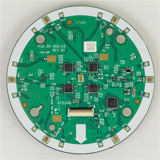
The two walls a microphone lives between
Every microphone spec sheet is a story about two walls and the room between them. The lower wall is the noise floor, the equivalent input noise, the faint electrical hiss the part makes with no sound present, and any sound quieter than that hiss is lost inside it. The upper wall is the acoustic overload point, the sound pressure level at which the output stops following the input and clips into distortion, and any sound louder than that is mangled. The distance between the walls is the dynamic range, and it is the spec that decides whether a single microphone can handle a scene before the loud parts distort or the soft parts vanish, which is why a high-dynamic-range part earns its premium in a world where the engineer cannot choose how loud the world will be. Signal-to-noise ratio is the same lower wall measured against a reference tone, so a part quoting 65 decibels of it has a quieter floor than one quoting 60, and the decibels are logarithmic, so a few of them are a large change in the faintest sound that survives. Sensitivity, quoted in decibels relative to a reference, only sets where the signal sits between the walls, not how far apart they are, and reading sensitivity as quality is the common mistake the two-wall picture is meant to cure.
Loud or soft, the wall it hits first is the one that matters.
Monitoring vibration on a machine
Vibration sensing swaps air for metal and points the same idea at a bearing. A motor that is healthy hums at a few frequencies it has always hummed at, and a fault writes itself into the vibration as new frequencies long before it is loud enough to hear or hot enough to smell. A crack in a bearing race rings at a frequency set by the geometry and the speed, often several kilohertz, and harmonics of the shaft rate carry their own story of imbalance and misalignment lower down. Catching it early is the whole premise of condition monitoring, the practice of reading a machine's vibration to schedule its repair before it fails. The method works by comparison: a baseline taken when the machine is known good, and every later reading checked against it for lines that were not there before. The catch is bandwidth: a sensor that reads only to a few hundred hertz, plenty for measuring tilt, is deaf to the kilohertz signature that announces the fault, so vibration parts for this job are built wide on purpose.
The ADXL1002 does wide-band vibration measurement, a single-axis accelerometer flat to around ten kilohertz with a resonance near twenty-one, and an analog voltage output that hands the raw waveform to whatever digitizes it. Its low noise density, a few tens of micro-g per root hertz, lets it resolve a small vibration riding on a large one, the faint bearing tone under the dominant shaft rotation. It spans plus or minus fifty g before it clips, headroom enough for the sharp impacts a damaged bearing throws off, and being a single axis it asks the installer to aim it along the direction the fault speaks loudest, usually radial to the shaft. The analog output is a deliberate choice: it puts the part where the host already has a good converter and wants the unprocessed signal for its own analysis, a high-frequency machine monitor reading the early signature of a failing bearing where the wide flat band is the entire value.
The IIS3DWB does wide-bandwidth vibration for condition monitoring, and it solves the same problem with a digital interface and three axes. It carries a flat response out past six kilohertz with an output data rate above twenty-six thousand samples a second, far beyond a general-purpose accelerometer, and streams the result over SPI into a buffer the host reads in blocks. The on-chip FIFO is the feature that makes it practical: the part fills the buffer while the processor sleeps, the host wakes to drain a batch and run its frequency analysis, and the average power stays low enough for a wireless monitor that lives on a battery bolted to a pump for years. It is the part built specifically for the predictive-maintenance node, where three axes, wide band and low average power all have to hold at once. Its range reaches plus or minus sixteen g and its noise density stays low across that wide band, so a small high-frequency tone survives next to the large low-frequency shake of the machine, and the three axes catch a fault whatever direction it drives the casing, sparing the installer a guess about which way to point it.
Bandwidth decides what you can see
The lesson that ties the microphones to the accelerometers is that bandwidth and noise floor together set what a sensor can perceive, and no amount of processing recovers what the sensor never captured. A microphone band-limited to telephone quality cannot be sharpened into high fidelity afterward; an accelerometer that rolls off at a few hundred hertz has thrown the bearing fault away before the firmware ever runs. The sampling has to reach the frequency the information lives at, which for voice is the few kilohertz of speech, for music the twenty kilohertz of hearing, and for a bearing fault the several kilohertz of the crack ringing. The sampling rate has to clear twice that top frequency or the information folds back as an alias that no filter downstream can unpick, so a part chosen with too narrow a band is a measurement that ends before the answer arrives. The roll-off is a slope and not a cliff, so a sensor flat to ten kilohertz is already fading at the very top of that band. Noise floor sets the other limit, the smallest signal that clears the hiss, and the two together draw the box the sensor can work inside. Everything downstream, the filters, the transforms, the thresholds, rearranges what is in that box and adds nothing from outside it.
Bit depth plays the part for amplitude that bandwidth plays for frequency. Each bit of resolution buys about six decibels of range between the smallest step and full scale, so a sixteen-bit stream carries far more of the quiet detail than an eight-bit one, and a microphone with a wide dynamic range is wasted behind a converter too coarse to hold it. The match runs both ways: a quiet sensor needs the bits to show what it heard, and the bits need a quiet sensor or they only resolve the noise in finer grain. A sixteen-bit capture of a noisy microphone holds no more real information than twelve, the lower bits filled with nothing but hiss.
The interface then sorts the rest. PDM and I2S carry audio, analog and SPI carry vibration, and the right one depends on what is waiting on the host: a codec with a PDM port wants the MP34DT05, a microcontroller wants the I2S parts, a board with a spare converter and an appetite for raw data wants the analog ADXL1002, and a low-power digital node wants the IIS3DWB with its FIFO doing the buffering. The sensor that fits the bus the host already speaks saves a translation layer that costs power, pins and code. A PDM part behind a chip without a PDM peripheral forces a software decimator that burns cycles the budget wanted elsewhere, so the bus match is a system decision before it is a sensor one.
So the choice runs from the signal back to the part. Air or metal sets microphone against accelerometer; the loudest and faintest the scene will produce sets the dynamic range; the highest frequency that carries information sets the bandwidth; and the bus already on the host sets the interface. Get those four right and the rest is arithmetic on a signal that came in clean. Get the band or the floor wrong and no cleverness afterward repairs a recording that never held the answer.






