- Products
- Marking
- Alternative
Taking a Resistor from the Spec All the Way to an Exact Part Number

Power semiconductor specialist, SiC and GaN · 15+ years in power electronics · adjunct lecturer in Grenoble and technical consultant
Somewhere on a reel in front of you sits a 0603 with 68X printed on it, three characters that already speak a complete sentence: code 68 on the EIA-96 ladder stands for 499, the letter X for a tenth, 49.9 ohms at one percent. Resistors have described themselves since the days of painted color bands; the marking only shrank as the body did. The ordering string says far more, and it says it first.
Omission is also a decision.
ERJ-3EKF1003V runs thirteen characters, and each one records a decision. The schematic that called for it made exactly one of them, 100 kilohms; the other twelve, the body, the film, the tolerance, the watts and volts it can stand, the way five thousand arrive on a reel, were made later, by someone, on purpose or by omission.
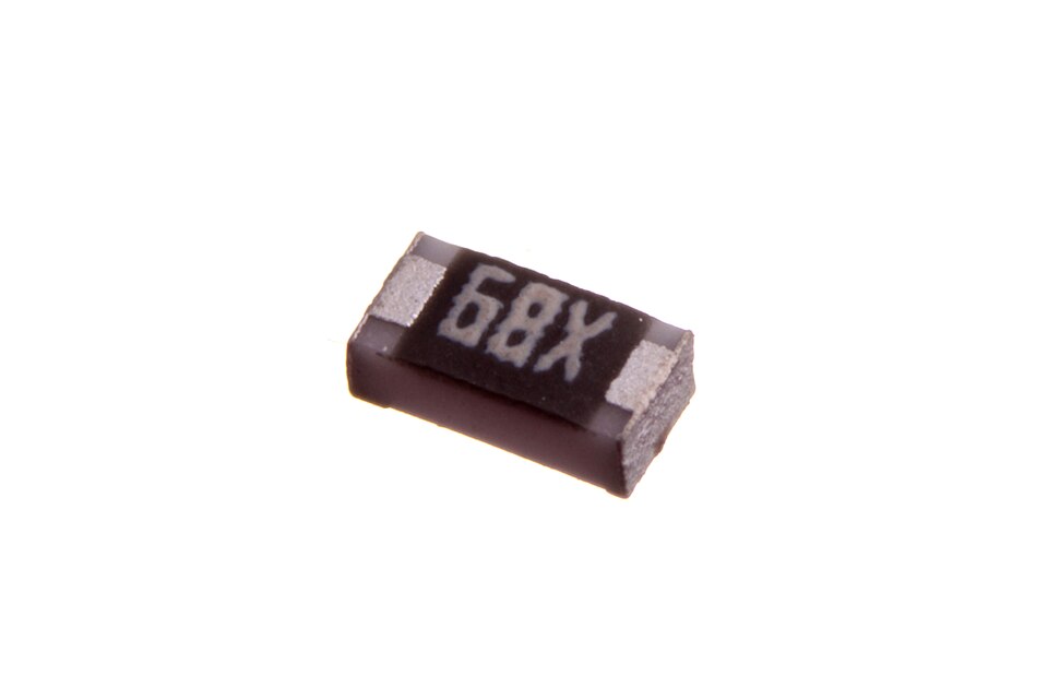
Photo: oomlout, CC BY-SA 2.0, via Wikimedia Commons
What a resistor is to the circuit
The printed value is a promise with conditions attached underneath.
One working model first, because the rest of the page leans on it. The resistor a circuit sees is the printed value multiplied by everything the print leaves out: the tolerance band it shipped inside, the temperature coefficient times the board's distance from 25 degrees, the slow creep of load-life drift, and at radio frequency a series inductance and a shunt capacitance listed in small type. A 100 kilohm 1 percent part with a 100 ppm film, on a board running 50 degrees warm, is a 100 kilohm plus or minus 1.5 percent part before it has aged a single day. Precision is a budget, and the print is only its first line.
The value comes off a ladder
Start with the one the schematic did make. Resistor values are not free numbers; they come from the preferred series in IEC 60063, spaced so that neighboring values meet at their tolerance limits. A 5 percent part lives on the E24 ladder, twenty four values per decade. A 1 percent part lives on E96, ninety six per decade, which is why a value like 49.9 ohms exists at all. If your divider math says 48.7 kilohms, the series is telling you to take 48.7 from E96 or round to 47 on E24, and to write down which one you did.
Tolerance is the F near the end of the string, and it is the cheapest letter in it. The price gap between 5 percent and 1 percent thick film closed years ago; across a reel of five thousand the difference rounds to nothing. The honest reasons left for 5 percent are stock you already own and dividers where the ratio washes the error out. Outside those, the tighter letter costs nothing and buys margin.
Take the F and spend your attention elsewhere.
Watts, and the volts nobody checks
The 3 in the string sets the body to 0603, and the body sets two ceilings at once. The first is the printed one: a standard thick film 0603 is rated around 0.1 W, an 0402 around 0.063 W, an 0805 around 0.125 W, always with the same fine print, full power up to 70 degrees C ambient and a straight line down to zero at the top of the range, 155 degrees C for this family. A part dissipating its full rating inside a warm enclosure is running derated whether you planned for that or not, so seasoned designers size for half the printed number and keep the rest as margin. The second ceiling is the one that gets skipped: rated working voltage, 75 V for this 0603. Power hides it. Put 75 V across 100 kilohms and the dissipation is 0.056 W, comfortably inside the wattage, while the part sits exactly at its voltage limit. Feed a 100 V rail into a megohm divider built on the same body and the dissipation is 0.01 W, a tenth of the rating, while the voltage limit is exceeded by a third. High resistance in a small body is the combination that fails this way, and nothing in the wattage column warns you.
When either ceiling is close, the fix is one character: a bigger size digit, or a different series letter.
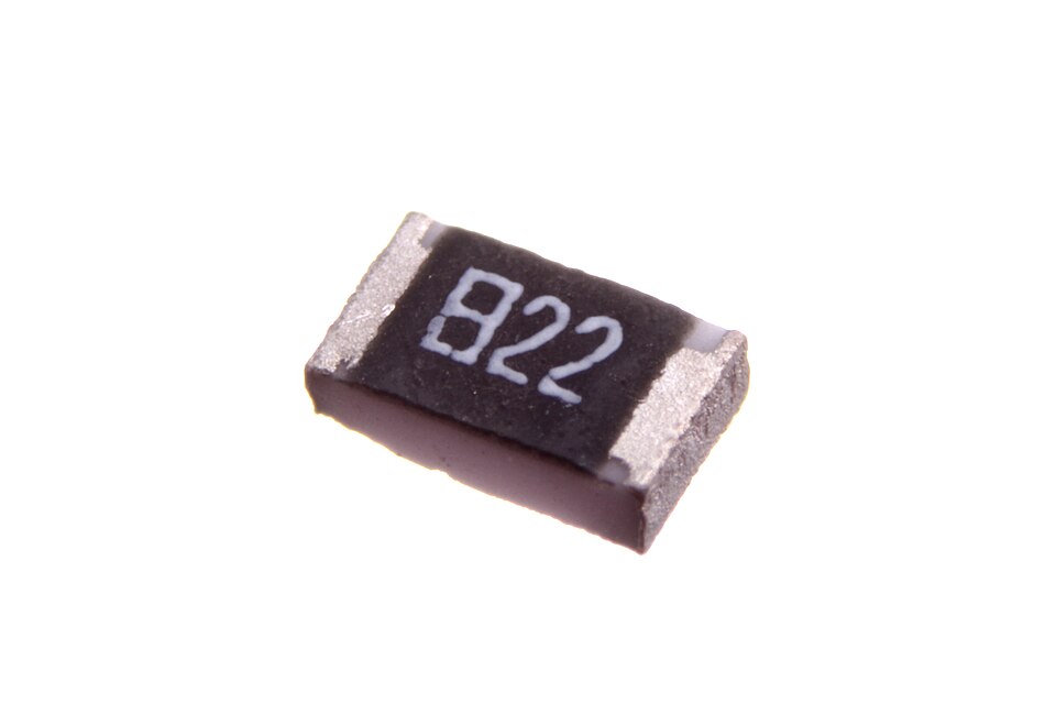
Photo: oomlout, CC BY-SA 2.0, via Wikimedia Commons
Surges are joules, watts are averages
The wattage rating is an average, settled over seconds, and surges refuse to read averages. A lightning-coupled transient or an inrush spike delivers its damage as energy, joules in microseconds, concentrated wherever the film runs thinnest, so a part loafing at a tenth of its rated watts can still be scarred by a pulse its average never noticed. Pulse-withstanding and anti-surge series exist for exactly this, reshaping the element so the energy lands on more material, and cylindrical and wirewound bodies absorb joules that would crater a flat chip. Rate a surge in joules first; the watt column only comes second.
The film families, one at a time
Thick film is the default the industry hands you: a fired metal glaze on an alumina body. For nine jobs out of ten it is the right default, which is exactly what makes the tenth job easy to miss.
Thin film is a different animal in the same body, a sputtered metal layer, smoother and more ordered than fired glaze, and the order shows up everywhere the glaze is rough. Temperature coefficient drops from the ±100 and ±200 ppm/°C of common thick film into the ±25 and ±10 ppm classes. Current noise falls. Long term drift tightens by something like an order of magnitude. None of that is visible at DC on day one, which is why the difference is so easy to undervalue.
Buy thin film where the resistor sits inside a measurement: sense dividers, gain setting around a precision amplifier, any node where a few hundred ppm of drift across temperature lands directly in the reading. Everywhere else the extra money does nothing you can observe.
In the string, the film hides in the series letters, not in a digit.
Past the films sit the shapes the films cannot serve. The MELF wraps a metal film around a cylinder, and the cylinder is the point: no corners in the element, so pulse handling and stability beat a flat chip of the same class, which is why MELFs keep their grip on automotive and metering boards decades after pick-and-place machines learned to hate their rolling bodies. Wirewound parts are resistance wire on a former, built to dump tens of watts or swallow surges, and inductive unless wound in opposing halves the way the noninductive types are. And metal foil sits at the far pole: a bulk alloy element with temperature coefficients in single-digit ppm and tolerances measured in thousandths of a percent, priced to match, bought for the one node in an instrument where the reading is the product.
The letters you learn about after a failure
Some series exist because of a specific way the standard part dies. Sulfur in the air, from gaskets, from certain rubbers and packaging, from particular industrial sites, creeps under the protective coat of an ordinary thick film part and converts the silver in its inner electrode to silver sulfide; the part drifts high and then opens, years in, with nothing visibly wrong on the board. Anti-sulfur variants change the electrode chemistry and cost a few extra characters in the ordering code. Anti-surge variants reshape the resistive element to survive pulses that would scar a standard film. AEC-Q200 is not a feature at all but a qualification regime, the automotive industry's way of demanding proof before the part rides in a car. Each of these lives in the part number as a series code that nobody reads closely until the day a board comes back.
Four resistors, one body
Resistor networks pack four or eight elements onto one substrate, and their selling point hides in the data sheet's second tolerance: the parts may be 1 or 2 percent absolute, yet they track one another within a fraction of that, because they were fired side by side from the same paste on the same ceramic. Dividers and instrumentation feedback care about ratio, and ratio is what a network sells. The shared body also quadruples placement speed and halves board area against four discretes, which is why volume boards grew fond of them long before precision did.
The price is the common pin, the bused-versus-isolated choice as one more letter in the string, and the single orientation rule chip resistors never had: the dot goes where the footprint says it goes.
A divider's error budget, worked
Numbers settle what adjectives argue about. Take a 2:1 sense divider built from two 1 percent thick film parts with 100 ppm films, on a board that runs 50 degrees above the bench. Initial tolerance contributes up to 2 percent of ratio error worst case, since the two parts can land on opposite ends of their bands. Temperature adds up to another 1 percent if the films drift apart across that rise, and load-life drift over the first thousand hours stacks a further fraction on top. Call it 3 percent of ratio uncertainty feeding an ADC that resolves a hundredth of that. The cure is written in the same string: F becomes B for 0.1 percent, the series letters move to a 25 ppm thin film, and the same arithmetic lands under half a percent.
The budget also shows where money gets wasted. A 0.1 percent part feeding a comparator with a 5 percent threshold is jewelry; a 1 percent part setting the gain of a 24-bit front end is sabotage. Match the letter to the node, never to the team's anxiety.
An application atlas, read backwards
Run the choices in reverse and the catalog sorts itself. Current sensing lives on bulk-metal shunts and four-terminal parts, because every microohm of solder would otherwise join the measurement. Gain setting around precision amplifiers belongs to thin film pairs that drift together. Gate drive and damping take small thick film values by the thousand. High-voltage dividers stack the HV-rated series or chains of ordinary parts, never one chip asked to hold a whole rail. Surge paths get the anti-surge and wirewound builds, radio-frequency terminations get thin film for its flatness, and the bleeder across a capacitor bank gets whatever wirewound brick survives the joules. Wherever the resistor sits inside a measurement, its letters get expensive.
The milliohm world runs on four wires
Below an ohm the part number changes dialect: the letter R becomes a decimal point, so R010 reads 10 milliohms and R001 a single one. Down here the enemy is everything around the part. A milliohm shunt soldered to two ordinary pads measures its own joints along with the current, and joints drift with temperature in a way no film does, so serious sense parts bring four terminals: two carry the amps, two tap the voltage from inside the element, and a Kelvin layout keeps those two pairs apart all the way to the amplifier.
Zero ohms deserves its own sentence. A 0 ohm jumper is a real product with a real rating, an amp or two of carrying capacity in an 0603-class body, used to hop traces on single-layer boards, to join grounds at one chosen point, and to hand test engineers a link they can unsolder. Its part number runs as long as anyone's.
Thermal noise comes free with the ohms
Every resistor generates noise by existing, and the formula carries no brand names: open-circuit thermal noise is the square root of 4kTRB, set by temperature, resistance and bandwidth alone. A 100 kilohm part at room temperature, watched across a 10 kilohertz band, hums at about four microvolts rms before any current flows, and no catalog letter reduces that number; the only levers are a smaller R or a narrower B, which is why low-noise front ends keep their first stage at low impedance. What the letters do govern is the second noise, current noise, the excess a part adds while carrying bias: thick film sits an order of magnitude or so above thin film there, with bulk foil lower again, so a microphone preamp and a gate damper can share a value and still have no business sharing a series.
Budget the free noise first; only then ask whether the excess noise of a cheaper film fits underneath it. That arithmetic takes one line and settles the argument before the layout starts.
The wattage has a temperature attached
The wattage was written at 70 degrees C; your enclosure was not.
The rating curve for a standard thick film chip runs flat to 70 degrees C ambient, then slides straight to zero at 155, which collapses into one small equation: available power is the rated number times 155 minus T, divided by 85. Run a sealed box at 90 degrees and a 0.1 W 0603 has 76 milliwatts left by the curve; apply the half-rating habit from the sizing section on top and the design budget is 38. The resistor did not get weaker. The print answered one question, what this part can survive, while the design needs the answer to a different one, what this part should be asked to do, and the distance between those two answers is the margin that keeps boards boring.
Above ten megohms, the board joins the part
High values fight their surroundings. From around ten megohms upward, the resistor competes with every parallel path the board offers, flux residue, fingerprints, humidity films across the solder mask, each of them a resistor nobody ordered, and in damp air the gigohm you placed can measure as a fraction of itself. The defenses are physical: a cleaned board, a guard ring driven at the node's own potential to starve the leakage of voltage, sometimes a longer package whose creepage buys distance. Voltage adds its own tax up here, because real films show a voltage coefficient, a slight fall of resistance as the field across the element grows, invisible in dividers and plainly visible in kilovolt strings.
The catalog answers with high-resistance and high-voltage series whose letters promise tighter coefficients and longer creepage, and the layout answers with copper. Both halves are mandatory; neither one substitutes for the other.
Reading ERJ-3EKF1003V
Now the string itself, left to right. ERJ is Panasonic's family of thick film chip resistors; the maker and the basic construction are settled before a single digit appears.
3 is this family's size code for 0603, the body that fixed both ceilings above. EK narrows the family to the general purpose precision series, and this two letter field is where the heavy decisions hide: the film build, the electrode, the qualification.
F is the tolerance letter from earlier, ±1 percent. 1003 is the value in the four digit code that precision parts use, three significant figures and a power of ten: 100 times ten cubed, 100 kilohms. Three digit markings work the same way with one fewer figure, which is what the 822 is doing for 8.2 kilohms; the smallest bodies, out of printing room, switch to EIA-96, two digits and a letter, which is the 68X standing for 49.9 ohms.
V closes the string with packaging: punched carrier tape, five thousand parts to the reel. It reads like trivia until a buyer orders the wrong suffix for a pick and place line.
None of this is new. The axial parts carry their value painted on the body in colored bands, a code old enough to have mnemonics; chip parts shrank the paint to three or four printed characters; the part number moved the rest of the spec off the body entirely and into the ordering string. Same instinct, three generations deep: make the part describe itself.
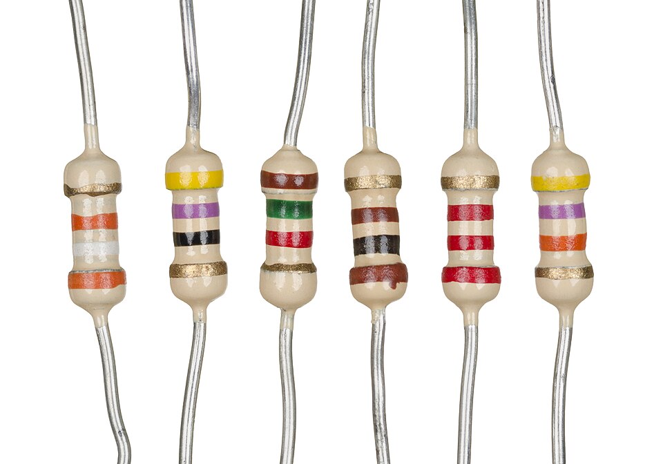
Photo: Evan-Amos, public domain, via Wikimedia Commons
One spec, two strings, and what goes on the BOM
Inside Panasonic alone, change EK to PA and the same footprint becomes ERJ-PA3F1003V: still 100 kilohms at ±1 percent on 0603 pads, now an anti-surge build listed at a quarter watt and 150 V, AEC-Q200 qualified. Two letters, double the voltage, two and a half times the wattage. Other makers run the same play in their own alphabets, so one physical spec usually maps to a handful of orderable strings across the market.
Put the exact string on the BOM, not the bare spec, and list the approved equals beside it. A line that reads 100k 1 percent 0603 invites whoever does the buying this month to remake the twelve decisions you just made, again, differently.
The board bends; the chip remembers
Chip components are ceramic, and ceramic forgives nothing. Depanelling a board along its V-grooves, torquing a mounting screw, pressing a stiff connector home, all of it bends the laminate a fraction of a degree, and a resistor soldered near that bending axis takes the strain straight into its body. The crack starts under a termination, invisible at inspection, and announces itself weeks later as a value that drifted or a circuit that opens when the enclosure is screwed shut and heals on the bench. MLCC capacitors made this failure famous; resistors attend the same funeral, only less often.
The countermeasures are layout habits, free when applied early. Keep chips out of the strip along break-off edges and around screw bosses; where a part has to live near an edge, set its long axis parallel to that edge so the bending strain works across the short dimension; and never let a rework iron quench a hot part with cold solder, because thermal shock writes the same crack in seconds instead of weeks.
None of this appears in the part number, which is the point: the thirteen characters describe the part as built, and the board decides how much of that survives assembly.
Receiving and testing without fooling yourself
Three minutes at the receiving bench will beat three weeks of field returns, every time.
In-circuit readings lie politely. A multimeter across a mounted resistor measures that part in parallel with everything else its net touches, so a 10 k reading on a 100 k part means the board is talking, never that the part has changed. Lift one end, or trust only out-of-circuit numbers; below a few ohms, use a four-wire measurement or accept that the test leads are part of the answer.
Receiving inspection for passives is short and sharp: reel label against the order, date and lot codes consistent, marking on sampled parts decoded back to the label, a meter check on a handful per reel. The three-minute habit catches the wrong-reel error that escapes every electrical test afterwards, because a flawless 10 k measures flawlessly even when the order said 100 k.
Counterfeits are rarer here than in silicon, but relabeled reels exist wherever a series variant carries a premium, anti-sulfur and automotive grades above all. The tell is paperwork: a reel without a traceable lot is a reel with a story, and the story is never one where you win.
Reels age politely
Resistors are the easiest tenants a warehouse keeps: no moisture-sensitivity clock, no charge to top up, no chemistry counting days. What ages is the interface, the solderability of the terminations, which oxidizes across years of storage and shows up on the line as joints that wet reluctantly, so old stock earns a solderability check rather than an automatic trip to the bin. The day-to-day discipline is about flow rather than preservation: reels joined with standard splice tape so feeders run through a changeover without stopping the machine, labels facing outward, first in first out by date code, and partial reels re-bagged with their identity attached, because an anonymous half reel of flawless parts is scrap with extra steps.
The reel label is the part's passport here as everywhere, and a splice that joins two different lots under one label is the single warehouse convenience the traceability rules refuse.
Where the catalog is heading
The bodies keep shrinking. The 01005 rides in volume phones and the 008004 now ships from a handful of makers, sizes where marking vanished long ago and the reel label is the only identity a part has, which moves the entire burden of truth onto receiving paperwork. Going the other way, wide-terminal chips turn the geometry sideways, putting terminations on the long edges so the same board area sheds heat into copper far faster and the wattage table gets rewritten.
The letters drift toward the strict end. Anti-sulfur terminations are sliding from option to default as makers tire of field-return forensics, automotive grades take a growing share of plain commodity values, and thin film keeps walking down the price ladder into sockets that bought thick film out of habit rather than arithmetic. The catalog keeps growing at both of its ends, while the method for reading it has stayed put.
Questions that keep coming back
How do I read the numbers printed on a chip resistor?
Three digits are two significant figures and a power of ten, so 103 is 10 kilohms. Four digits give three figures the same way, so 1003 is 100 k. Two digits plus a letter is EIA-96 for 1 percent parts, the 68X of Fig 1, code 68 for 499 and X for a tenth: 49.9 ohms.
My 0402 has no marking at all. Is that wrong?
It is normal. From 0402 down, makers ship bare faces; the identity lives entirely on the reel label, which is exactly why the receiving check earns its three minutes.
Does 1 percent cost meaningfully more than 5?
On commodity thick film, no; the gap closed years ago and rounds to nothing across a reel. The remaining honest reasons for 5 percent are stock on hand and dividers where the ratio washes the error out.
Can I parallel two parts to land between E96 steps?
Yes, and it is routine. The combined tolerance stays in the class of the parts used, their temperature coefficients average toward each other, and the price is two placements and two BOM lines instead of one.
What is a zero-ohm resistor for?
Crossing traces on single-layer boards, joining grounds at one deliberate point, and giving production a link that a soldering iron can open. It carries a real current rating, on the order of an amp or two in small bodies.
Do resistors age?
Slowly, yes. Thick film at full rated load typically drifts by well under a percent over its first thousand hours, with thin film an order tighter; precision nodes carry that line in the error budget.
What does R010 mean?
The R is a decimal point in the low-value dialect: R010 is 0.010 ohms, 10 milliohms, the territory of current-sense shunts and four-terminal layouts.
Do chip resistors have a polarity?
No; either orientation works. The one cousin that cares is the resistor network, whose common pin has to land on the right pad.
Why did my resistor fail open instead of short?
Film elements crack and burn toward open circuit by nature, a gentle failure direction that fusible resistor series turn into a feature: a part designed to die open and protect the rail behind it.
Is an 0805 dearer than an 0603?
Per piece, barely; the costs that matter are board area and one more line item in stores. What the bigger body buys is wattage and working voltage, as the ratings ladder in the sizing section shows.
Can I use an E96 part where the schematic names an E24 value?
In practice, yes: makers build their 1 percent ranges to cover the popular E24 values alongside the E96 ladder, so 4.7 k exists at 1 percent even though 4.75 k is its formal E96 neighbor. Put the exact ordered value on the BOM and the question never comes back.
Does anyone still use color bands?
Through-hole survives wherever power, surge duty or repair access keeps it alive, and those bodies still wear bands. On reels the bands died with the cylinder; printed marking and the reel label took over.
What does AEC-Q200 put a resistor through?
A qualification gauntlet rather than a feature: temperature cycling, humidity with bias, mechanical shock and vibration, solderability and ESD, run on documented lots with reported results. The letters cost money because the evidence behind them does.
Getting the reel
The last step involves no engineering at all: matching the string to a reel that exists. Commodity values are rarely the shortage; the exact series variants, anti-sulfur, anti-surge, automotive grades, are what go allocation first when the market tightens. In Fortune Electronics quotes against the exact string, ERJ-3EKF1003V and its siblings included, confirms the packaging suffix a production line needs, and sources approved equivalents when a series variant runs dry. Send the thirteen characters; the work is already in them.
Ratings quoted here, 0.1 W and 75 V for the ERJ-3EK 0603 and the figures for its PA sibling, reflect current maker and distributor listings; confirm against the Panasonic data sheet for the revision you buy, since series ratings shift between revisions.