Free Shipping Over$200

- Products
- Marking
- Alternative

Laying Out a Microphone Array for Far Field Voice
Laying Out a Microphone Array for Far Field Voice
A far field voice product succeeds or fails before the model hears a word. The microphone array decides whether the signal arrives with usable timing, level, phase relationship and noise separation. A good speech algorithm can compensate for a lot, but it cannot recover geometry that hides one microphone behind plastic, routes a noisy rail beside the preamp path, or places the array so close together that direction information collapses.
The layout work is therefore a system decision. It includes microphone type, number of channels, spacing, acoustic opening, enclosure wall, gasket, clocking, power filtering, digital interface, connector direction and the way firmware will identify each channel. Treating the microphones as small parts sprinkled around a board usually creates a product that sounds fine on the bench and weak in a room.
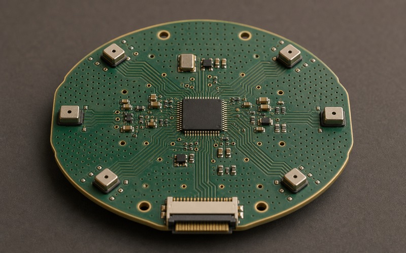
Start With the Voice Distance and Use Case
Far field voice does not mean one fixed distance. A desk speaker, control panel, intercom, appliance, conference device and wall mounted sensor all hear different rooms. The expected distance, user direction, background noise and enclosure orientation should be written before the microphone count is chosen. A board for near-field commands should not be copied into a product that must hear across a kitchen.
The use case also decides whether direction matters. A simple wake-word product may only need reliable pickup from a broad area. A product that steers a beam, rejects a fan or tracks a talker needs better geometry and more disciplined channel matching. The selection record should state whether the array is used for gain, direction, noise rejection, echo cancellation or a mix of those jobs.
If the product includes a speaker, the microphone plan must include the echo path. The speaker position, cavity, grille and volume level affect what the microphones hear. A microphone array that is laid out without the playback path in mind can make acoustic echo cancellation much harder than the electronics schematic suggests.
Choose the Number of Microphones Deliberately
Two microphones can support simple direction cues and some noise reduction. Four microphones give more room for beamforming and fault tolerance. Six or more can improve spatial information, but they add routing, power, clocking, test time and mechanical risk. More microphones are useful only when the enclosure and firmware can preserve the timing and level relationships between channels.
The count should match the physical size of the product. A tiny board with many microphones crowded into one corner may measure as several channels but behave like one poor aperture. A larger device can use perimeter placement to separate channels and improve direction cues. The spacing should be reviewed against the frequency range that matters for speech, not against a visual desire for symmetry alone.
Keep a fallback plan. If one microphone is optional, note what the firmware loses when it is removed. If the array needs all channels to work, the production test should catch a blocked port, missing part or swapped channel before the unit leaves the line.
Place the Acoustic Ports Before Routing the Board
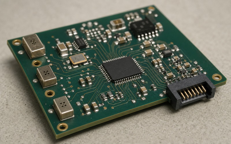
The acoustic port is the real input. The MEMS package outline matters, but the port position and enclosure opening decide what reaches the diaphragm. Place microphones so each port has a clear path through the housing, with enough clearance from ribs, screws, adhesive, foam, labels and cosmetic mesh. A port hidden under a lip can look correct on the PCB and fail in the assembled product.
Use the mechanical design to define keepout regions. Around each microphone, mark the air path, gasket area, case wall, water or dust membrane and any shared cavity. If a gasket seals poorly, the microphone may hear leakage from inside the product instead of the room. If a membrane covers one port differently from the others, channel matching changes.
Port orientation should also be consistent. A top-port and bottom-port microphone can both be useful, but swapping between them late in the project changes holes, assembly and acoustic behavior. If an alternate microphone has a different port location, it should not be treated as a simple purchasing change.

Keep Channel Timing and Routing Matched
Digital MEMS microphones reduce the analog noise path, but their timing still needs care. Clock and data routing should be consistent, and the channel order should be documented in the firmware record. A swapped left-right pair or a different data-slot assignment can make beamforming appear broken even when the parts are soldered correctly.
Matched routing does not require every trace to be mathematically identical for a slow audio stream, but it does require predictable clock quality, clean returns and a layout that does not put one microphone beside a noisy switching node while another sits in a quiet corner. The array should be reviewed as a set of sensors, not as six isolated footprints.
When analog microphones are used, the matching burden increases. Bias, gain, filtering, trace impedance and nearby noise sources can create channel differences before the codec samples the signal. The same board can pass a single-microphone test and still perform poorly as an array if channel gain or phase is not controlled.
Control Power, Clock and Ground Noise
A microphone array often sits near radios, displays, motors, LEDs, speakers or DC-DC converters. Those parts create noise that can enter through the supply, ground, clock or acoustic path. Local decoupling should be close to each microphone or microphone group, and the shared rail should be checked while the rest of the product is active.
Clock quality matters because it sets the sampling reference. A poor clock, a long unshielded route or a noisy return can create artifacts that are difficult to separate from acoustic noise. Keep the clock source, routing and load assumptions in the design record. If the array shares an audio processor, codec or bridge, the timing relationship should be verified at the same sample rate used by the algorithm.
Ground stitching around the microphones can help control return paths, but it should not block the acoustic path or create assembly traps. The mechanical and electrical teams should agree on where copper, openings, gasket pressure and screws are allowed around each port.
Make the Connector and Assembly Direction Real
The microphone board usually connects to a host board through FFC, board-to-board connector, cable or soldered flex. That connector should face the real assembly direction. A connector that points into the board center or toward a housing wall can force a bend that changes assembly yield or presses on the acoustic area.
Channel order should follow the connector pinout and the firmware map. If the cable can be reversed, keyed, latched or folded, the design record should show the intended orientation. A field failure caused by a poorly supported flex can look like a microphone or algorithm problem when the real issue is mechanical strain.
Test access also belongs in the layout. A production fixture may need to play calibrated sound, read all channels and confirm channel identity. If test pads are hidden under the flex or inside the acoustic chamber, diagnosing a weak channel becomes slow and subjective.
Check the Enclosure as Part of the Sensor
The enclosure is part of the microphone system. A grille, fabric, gasket, waterproof membrane, foam pad or cosmetic cover can attenuate high frequencies and create channel mismatch. The board should be validated inside the real mechanical stack and with the same acoustic path the shipped product will use.
Room tests should include directions and distances that match the product promise. Test a quiet room, fan noise, nearby speaker playback, handling vibration and the expected mounting position. If the product can be wall mounted, table mounted or handheld, each position may change the acoustic shadow around the ports.
Keep the test files and acoustic setup repeatable. A voice sample played from a phone across the room is not enough evidence for a design release. The team should know the source level, distance, angle, noise condition, sample rate, firmware build and enclosure revision used for approval.
Define Substitution Risk Around Geometry
Microphone alternates are risky because the electrical line item is only part of the behavior. Sensitivity, signal-to-noise ratio, acoustic overload point, frequency response, port location, package height, startup time, current, interface timing and supply voltage can all affect the array. A substitute that matches the bus protocol can still change the beam pattern.
For each approved microphone, keep the port orientation, footprint, gasket assumption and channel calibration in the record. If an alternate changes any of those items, it needs acoustic retest. If the product uses a membrane or special grille, the alternate should be checked through that same stack.
Procurement should receive a clear boundary. Approved alternates should state which board revision, enclosure revision and firmware calibration they match. Without that boundary, a small microphone substitution can reach production and make the product hear differently from batch to batch.
Calibrate the Array With the Same Channel Map Used in Production
Even a well placed array needs a repeatable calibration and verification path. The engineering team should record which physical microphone becomes channel one, which direction is treated as the product front, which sample rate is used and which firmware build owns the gain or delay compensation. If the connector, flex cable or firmware channel map changes, the calibration record should be revisited.
A simple production check can still be meaningful. The fixture can play a controlled sound from a known direction, confirm that all channels respond, check that one channel is not blocked or swapped, and compare level balance within a defined limit. The goal is not a full acoustic chamber test for every unit; the goal is to catch assembly errors that would break the array before the product reaches the customer.
Field service and future sourcing also benefit from this record. When a microphone alternate, enclosure revision or gasket material changes, the team can compare the same channel order, test sound, direction and firmware setting. That keeps the array decision tied to evidence instead of memory from an early prototype.
Final Layout Checklist
Before approving a far field microphone array, confirm the use distance, microphone count, spacing, port exposure, enclosure opening, gasket condition, rail noise, clock quality, connector direction, channel map and production test method. Verify the array inside the mechanical stack and with the speaker active when the product includes playback.
The strongest array layout is not the most crowded board. It is the one where every microphone has a known acoustic path, a predictable electrical path and a documented role in firmware. That evidence keeps the design useful when the enclosure changes, the microphone alternate list grows or the next production build needs a repeatable check.