Free Shipping Over$200

- Products
- Marking
- Alternative

MAX98357A Driving a Small Speaker Straight From I2S
MAX98357A Driving a Small Speaker Straight From I2S
The MAX98357A belongs to a useful class of parts: a small digital-input Class-D amplifier that can take an I2S audio stream and drive a modest speaker without a separate audio DAC, line amplifier or analog volume stage. That makes it attractive in voice prompts, compact smart speakers, handheld test equipment, user-interface tones and edge devices that need a simple speaker path beside microphones, sensors and a host controller.
The part is easy to describe, but the board decision still deserves a full review. The amplifier sits where a digital timing problem, a power integrity problem and an acoustic load all meet. If the I2S timing is loose, the sound path can glitch. If the supply and output routing are weak, the board can radiate noise or clip early. If the speaker load is chosen carelessly, the electrical design may pass on the bench and fail inside the enclosure.
Use a Digital Input Amplifier When the Signal Path Is Simple
An I2S-input speaker amplifier is a good fit when the host already produces the audio stream and the product needs a single small speaker output. The host may be an MCU, application processor, wireless module or audio bridge. In that case, the amplifier can remove the need for a separate DAC and analog gain stage, reducing board area and removing one sensitive analog route.
The same choice is weaker when the product needs several analog sources, a headphone path, line output, microphone capture through the same device or precise analog level control. Those needs often point to a codec or a fuller audio subsystem. The first selection question is therefore functional, not parametric: does the board need only a speaker output, or does it need a broader audio hub?
The I2S format should be checked before the package is approved. The bit clock, word select, data alignment, sample rate family and mute behavior need to match the host firmware. A simple amplifier can still create debug time when the audio frame format differs from what the firmware team expects.
Start With the Speaker Load
The speaker is not an afterthought. Its impedance, power rating, sensitivity, enclosure volume and cable length decide how hard the amplifier must work. A small 4 ohm speaker asks for more current than an 8 ohm speaker at the same output voltage. A sealed enclosure can make a speaker sound quieter than the bench test suggests, which may tempt the team to raise gain and stress the supply.
Keep the speaker choice and the amplifier approval together. The record should name the impedance range, expected acoustic level, enclosure assumption and the maximum output setting used during validation. If the mechanical team changes the speaker, grille or cavity later, the audio and power tests should be repeated.
Speaker wiring also changes the review. A short cable inside an enclosure behaves differently from a longer harness that exits a board. The connector orientation should face the cable path, and the output traces should not force the speaker current to run beside sensitive microphone, sensor or RF lines.
Give the Output Current a Clean Path
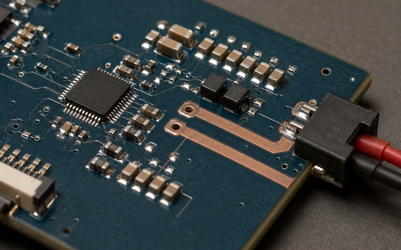
A Class-D output is efficient because it switches. That switching current needs a compact path from the amplifier pins to the speaker connector and back through the return structure. Wide copper near the output can reduce loss and temperature rise, but the return path must be just as deliberate. A pretty pair of output traces does not solve a poor ground path.
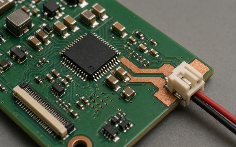
Place the speaker connector at the board edge when the enclosure wiring allows it. The cable should leave the PCB in the direction it will take in the real product. Turning the connector toward the board center creates assembly stress and can put the high-current speaker path across unrelated circuitry.
If the layout uses ferrite beads or a filter network, keep those parts close to the amplifier or connector according to the chosen EMI strategy. Record the filter values with the speaker and cable assumption. A substitute bead, inductor or capacitor can change emissions and audio behavior even when the amplifier part number stays the same.
Protect the Supply From Audio Bursts
Audio current is bursty. A status beep, voice prompt or alert tone can pull a short pulse from the rail while the rest of the system is waking a radio, display or sensor. The amplifier supply should be reviewed against that real operating sequence, not against a quiet single-tone bench case.
Local decoupling belongs close to the amplifier supply pins. The upstream regulator must handle the peak and recovery behavior without dragging down the host, memory, microphone or wireless rail. If the board uses a shared 5 V or battery-derived rail, measure the dip during the loudest expected prompt and during startup.
Power sequencing also deserves attention. The amplifier may need a clean shutdown or mute state while the host boots. A pop at startup can become a customer complaint even when the electrical design is otherwise safe. Firmware mute timing, enable pin behavior and rail ramp should be verified together.
Keep I2S Timing and Firmware Behavior Reproducible
The digital interface reduces analog noise exposure, but it does not remove timing discipline. Bit clock, left-right clock and data should have clean routing, clear ownership and a known startup state. The host should define what the data line does during reset, sleep and sample-rate changes.
Firmware should own volume mapping and mute behavior in a way that can be repeated. A user-interface tone path may be simple at first, then gain prompts, alarms and confirmation sounds over time. If each firmware change adjusts gain by trial, the approved hardware limit can be forgotten.
Keep one repeatable audio test set with the project. It should include silence, a short click-prone transition, a voice prompt, a high-level tone and a low-level tone. The same files should be used after a speaker change, regulator change, enclosure revision or amplifier alternate review.
Review EMI Before the Enclosure Is Closed
A switching speaker output can disturb radio, microphone and sensor sections when the board is dense. The risk is higher when the speaker cable is long, routed near an antenna or placed beside a high-impedance analog input. The selection record should call out those physical relationships before the board is treated as solved.
EMI review starts with placement and current loop control. Keep the amplifier, output path, filter parts and connector in a compact area. Keep the return path predictable. Avoid sending the output pair through quiet analog territory. When an RF module or antenna shares the product, test the speaker at the loud levels the user will actually hear.
The enclosure can move the problem. A cable that was harmless on an open bench can sit next to an antenna, microphone flex or sensor lead after assembly. Acoustic validation and emissions screening should happen with the intended cable routing and with a mechanical setup that represents the final cable position.
Check Thermal Behavior in the Real Use Case
Class-D efficiency helps, but small packages still need a thermal path. Temperature depends on speaker impedance, duty cycle, ambient temperature, copper area and enclosure airflow. A short confirmation beep is easy; a repeated voice instruction or alarm loop is a different load.
Measure temperature near the amplifier after the longest expected playback event. If the product can repeat prompts, test that repetition. If the board sits near a warm processor, radio or charger, include that heat source in the review. The approval should not depend on a cool open-board condition that the product will never see.
Copper around the amplifier should be treated as part of the component decision. A package that works on one board may run hotter on a smaller revision with less copper or fewer vias. A substitute amplifier should be checked with the same copper, enclosure and speaker assumptions.
Make Substitution Rules Specific
A pin-compatible or functionally similar I2S amplifier is not automatically safe. The substitute review should compare supply range, output power conditions, supported I2S formats, enable behavior, gain configuration, pop suppression, protection features, thermal performance and package footprint.
The small passive network around the amplifier also matters. Decoupling capacitors, ferrite beads, output filters and connector footprint can limit the alternate list. If an alternate requires a different filter, gain strap or enable timing, it belongs in an engineering review rather than a purchasing swap.
Purchasing and engineering should share one approval boundary. The record should state the speaker impedance used for testing, the rail voltage, the expected output level, the accepted package, the connector orientation and any approved alternate parts. Without that boundary, a lower-cost amplifier can enter the design while changing startup sound, thermal margin or emissions behavior.
Keep Production Test Simple but Meaningful
A small speaker amplifier should have a production check that proves the electrical path without turning the fixture into an audio lab. The test can confirm host communication, enable behavior, rail current during a short playback event, absence of a shorted speaker output and basic acoustic response. A microphone in the fixture may be enough for a go or no-go sound check when the product design supports it.
The test should also protect against assembly mistakes. Reversed or poorly seated speaker wiring, a connector pressed in the wrong direction, missing decoupling parts, solder bridges around the amplifier pins and a damaged output filter can all pass a visual inspection from the wrong angle. A short controlled playback pattern can expose several of those faults quickly.
Keep the factory limits tied to the same speaker and enclosure assumptions used during engineering validation. If the production line later changes the speaker cable, connector, fixture microphone distance or acoustic opening, the limit should be reviewed rather than copied forward. A clear test note keeps the amplifier decision connected to the product that will actually ship.
Final Selection Checklist
Before approving a MAX98357A class device, confirm that the product needs a simple digital speaker output rather than a full codec. Verify the I2S format, speaker impedance, rail voltage, output copper, filter parts, mute timing, thermal path and connector direction. Then test the audio path inside the enclosure or in a mechanical setup that matches the cable route.
Keep the test evidence with the board revision. It should show the host format, audio samples, supply waveform, maximum playback case, thermal result, speaker part and any EMI or coexistence findings. That evidence makes future alternates easier to judge.
The right amplifier choice is the one that keeps the audio path simple while leaving no hidden assumptions in the board, firmware or supply record.