SGTL5000 as a Low Power Audio Codec for a Voice Device
A voice device can look finished once the microphone, processor and speaker path are named, yet the audio codec often decides whether the design behaves like a product or like a lab board. The SGTL5000 class of low power codec sits at that boundary. It receives an analog microphone signal or line input, converts the signal into digital audio for the host, accepts playback data from the host, and drives the analog output path with the gain, filtering and power states that the rest of the design depends on. Selection is less about choosing a familiar audio part and more about checking the full capture and playback chain around it.
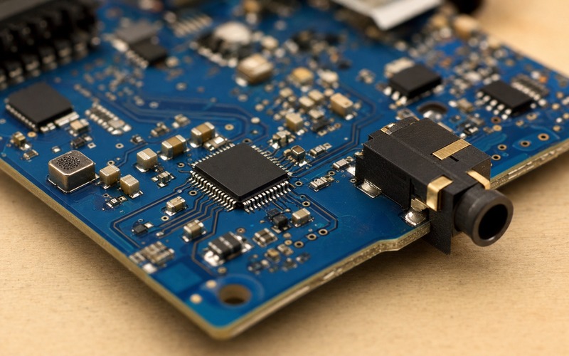
Start With the Audio Job on the Board
The first question is the product role. A smart remote, handheld recorder, access panel, wearable reader and small assistant unit can all use a low power codec, but they place different pressure on the part. Some need one microphone and a headphone output. Some need line level audio, a small speaker amplifier stage outside the codec, or a path that stays quiet while the host sleeps. The SGTL5000 should be reviewed against those operating modes before the schematic is copied from a reference design.
A codec is a mixed signal boundary. It owns the analog input conditioning, the ADC path, the DAC path, the headphone or line output, the digital serial interface and the control registers that set gain and routing. If the design treats it as a black box between a microphone and I2S pins, many decisions are left for the bring-up bench. The board team should write down the capture source, playback load, host interface role, power rail plan, mute behavior and low power sequence before approving the part.
Match Microphone Input and Gain Range
Voice capture starts at the microphone and the bias network. If the microphone is analog electret or MEMS with an analog output, the codec input has to provide the right bias, impedance and gain range. The expected speech level, acoustic path loss, enclosure opening and noise target should guide gain setting. A gain range that looks large in the register table can still be hard to use if the board injects supply noise, if the microphone port sits near vibration, or if the software applies digital gain after the ADC has already clipped.
Engineers should check whether the microphone input needs single ended or differential routing, which coupling capacitors are required, how the bias rail is filtered, and where the input return path flows. The input traces deserve the quietest part of the board that the mechanical design allows. Keep them away from speaker current, buck inductor fields, display clocks and wireless transmit bursts. A low power codec cannot recover an input signal that has already picked up board noise before it reaches the pin.
Review the ADC Path as a Measurement Chain
The ADC inside the codec is part of a measurement chain, even when the application is speech. The usable result depends on microphone sensitivity, analog gain, anti alias filtering, sampling rate, clock stability and digital word format. A voice model or speech recorder receives whatever this chain produces. A clean schematic symbol does not prove that the sampled signal has enough headroom during loud speech or enough noise margin during quiet speech.
Testing should include silence, near speech, far speech and product activity that happens during recording. If a display refresh, wireless transmit window or motor action creates periodic tones in the audio file, the codec placement and routing need another pass. If gain is set high to improve far voice capture, the team should check loud speech and enclosure resonance as well. A useful validation file includes raw captures at the codec output, with processed audio kept as a separate review layer.
Check Playback Output Before Choosing the Load
The SGTL5000 class codec can support analog playback paths, but the board still has to define the load. A headphone output, line output and external amplifier input have different requirements for coupling, impedance, pop control and routing. The data sheet output rating should be compared with the real load and with the output path that the product will use. If a speaker is needed, the codec output may feed a separate amplifier, and that amplifier brings supply, thermal and EMI questions of its own.
Output routing should avoid the microphone input area unless the product has a clear separation plan. Feedback from the output path into the input path can show up as echo, oscillation, hiss or unstable automatic gain behavior. The output connector, jack or cable should sit at the board edge with a real insertion direction, strain relief plan and ground reference. A connector that points toward the middle of the board is a layout warning because it rarely matches service, enclosure or cable routing needs.
Put the Digital Audio Interface in the Timing Plan
The codec and host must agree on the audio serial format. I2S, left justified, right justified, DSP modes and related framing choices are easy to describe in firmware notes, but the clocks and word length still have to match at the pins. The review should identify which device is clock master, which clocks are present in sleep, which sample rates are allowed, and how firmware reconfigures the path after wake. A mismatch can sound like silence, channel swap, bursts of noise or random capture faults.
Clock quality matters because the part straddles analog and digital sections. The master clock or derived bit clocks should avoid noisy routing regions and should not cross split return paths. If the host provides the clock, the route from processor to codec belongs in the audio timing budget. If a local crystal or oscillator is used, place it with a clean return path and keep it away from power switching fields. Low power voice products often fail in transition states, so the timing plan should include suspend, wake and mute events.
Design Power Rails Around Audio Noise
Power selection is part of audio selection. The codec may use separate analog, digital and I/O rails, each with its own range, sequencing and decoupling needs. A rail shared with wireless PA current, LED drivers or a noisy switching regulator can push unwanted tones into the capture or playback path. Local decoupling has to sit close to the pins, with a short return path and a clear relationship to the analog ground area.
Low current in sleep does not excuse a weak power plan. The part may wake often, change gain, enable output drivers and move between sample rates. Each event can draw transient current and disturb a nearby input if the rail and return layout are poor. Designers should review regulator noise, power state control, reset state and register restore sequence. A clean low power path is a system behavior, not a single current number in the table.
Place the Codec as a Mixed Signal Part
Placement should make the signal story visible. The microphone input should enter from a quiet side, pass through bias and filtering near the codec, and stay away from the output load. The headphone, line or amplifier feed should leave toward the connector or amplifier zone without crossing the input area. The digital audio and control buses should head toward the processor with a clean return path. Decoupling capacitors and any clock component should sit close enough to do their job.
A small package can still consume layout time. Pin escape, via placement, analog decoupling, digital decoupling and test access have to fit without forcing fragile routing. If a substitute codec changes pin order, package pitch, exposed pad, rail grouping or control bus behavior, the board may need more than a symbol edit. Package review should include the assembly process, inspection access and the way the connector or cable exits the enclosure.

Check Control Registers and Firmware Ownership
The hardware choice must match the firmware model. The codec may need register writes for clocking, gain, input route, output route, mute, bias control, power state and digital audio format. During development, those writes are often changed until the product sounds right. For production, the register set needs to be fixed, documented and tested across reset, sleep and wake. A missing mute bit or a gain value restored in the wrong order can create noise even when the schematic is correct.
Firmware should log codec initialization, clock state, sample rate, input route and any error condition during audio start. Hardware validation should observe rail behavior and clock stability at the same events. This shared log is useful when the first captured samples after wake contain clicks, when one channel disappears, or when the host audio port starts before the codec has settled. A codec is selected by hardware, but it is approved by hardware and firmware together.
Separate Codec Choice From System Audio Features
A low power codec does not replace every audio function. It will not solve acoustic echo by itself, and it will not fix a speaker path that has no margin. It does not make a poor microphone location usable, and it does not turn a noisy ground plan into a quiet recorder. Its job is to provide a controlled conversion and analog routing section that the rest of the voice device can rely on. That boundary should stay clear during design review.
This is also where feature creep can create trouble. A team may start with one microphone and later ask for line input, stereo playback, jack detect, higher sample rates or always listening operation. Each addition changes power, routing, register and validation needs. The selected codec should have enough confirmed capability for the product plan, while the board should avoid unused options that make layout and bring-up harder without a real requirement.
Use Substitution Review Before the BOM Is Frozen
An alternate codec has to be checked at several levels. The first level is function: microphone input type, ADC and DAC capability, output driver, digital audio modes, control interface and sample rate support. The second level is electrical: rail voltage, I/O level, clock requirements, input common mode, output load and noise behavior. The third level is physical: package, pinout, land pattern, exposed pad, decoupling locations and the way audio connectors leave the board.
After that, firmware impact has to be reviewed. A new codec may need a different register map, startup sequence, mute behavior or power state model. That can be fine when planned early, but it is risky after the audio path has already been tuned. Buyers should request exact part number checks with package suffix and approved alternatives. Engineers should keep the validation files and register settings that made the first part acceptable, so an alternate can be judged against evidence rather than guesswork.
Final Component Selection Checklist
Before release, confirm microphone type, bias needs, input gain range, ADC headroom, output load, digital audio mode, clock ownership, rail voltage, sequencing, package and connector direction. Check that the input path stays quiet, the output path leaves the board in a serviceable direction, and the digital interface reaches the host without crossing noisy regions. Record silence and speech while the product runs its normal display, wireless, motor and power state activity.
If the SGTL5000 class codec remains the approved choice after those checks, document the exact orderable part, package suffix, rail assumptions, register setup, layout constraints and approved alternate review path. That record helps engineering and sourcing protect the audio path through prototype changes, vendor review and production transition. In a voice device, the codec is a small part, but it is the place where acoustic reality becomes digital data and where playback returns to the physical product.