ADAU7002ACBZ-R7 Turning a PDM Microphone into I2S
A PDM microphone looks convenient until the rest of the audio path has no native PDM input. The part then has to sit between two timing worlds: a bitstream coming from a tiny digital microphone and an I2S receiver that expects framed audio words. The ADAU7002ACBZ-R7 class of bridge is selected less as an audio accessory and more as a boundary part. It decides where the microphone clock comes from, how close the bitstream can stay to its source, how the audio rail is decoupled, and whether a voice front end can be routed without dragging noise into the processor side.
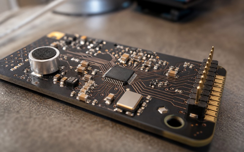
Start With the Microphone Signal Shape
A PDM microphone does not hand over samples in the same way a codec or an ADC does. It sends a high-rate one-bit stream whose density represents the acoustic signal after modulation inside the microphone package. That stream is useful because the microphone can stay small and digital, but it is not the same format used by many processors, audio serial ports and voice capture blocks. If the host side expects I2S, the bridge has to decimate, frame and time that stream before the data becomes ordinary left/right audio words. Selection starts by checking whether the microphone output, the intended sampling rate and the host audio port can share a clocking plan without extra logic.
The first practical question is where the PDM clock will be generated and how it will reach the microphone. A clock that crosses a noisy board area before it reaches the microphone can show up as jitter, coupling or strange edge timing at the input of the converter. A short route from the bridge to the microphone, with local return continuity and local decoupling, is safer than treating the PDM line as a casual GPIO trace. The layout does not need to look dramatic; it needs to be short, referenced and separated from power switching edges.
Check What the Bridge Must Deliver to the Host
The I2S side is less mysterious, but it can still fail when the format assumption is wrong. The host may expect a particular bit clock relationship, left/right clock polarity, word length or channel order. A PDM-to-I2S bridge should be reviewed against the host controller before the schematic is treated as closed. The review has to go past pin connection. The host has to receive the framed stream at the planned rate while the firmware, DMA path and audio pipeline all agree on the same frame structure.
This matters for voice AI because the capture path is often judged late. A prototype can record speech well enough during a bench test, then fail when the firmware switches modes, when a low-power state changes clocks, or when a second audio source is added. The bridge should be placed in the system diagram as a timing participant. The host has to know whether it is master or slave, how bit clock and frame clock are produced, and what happens when capture is muted, suspended or restarted.
Keep the PDM Lines Short and Quiet
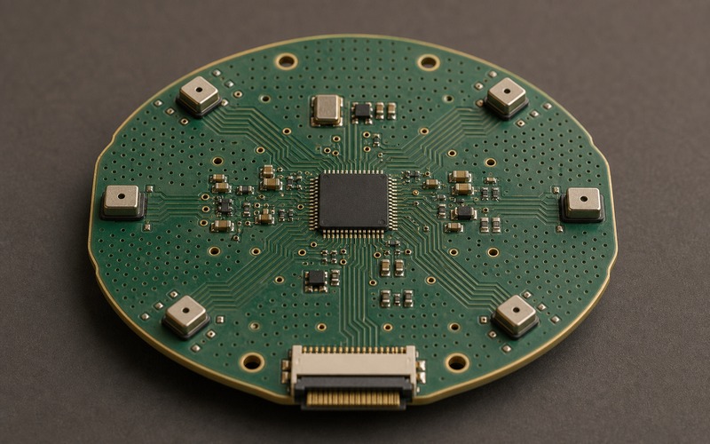
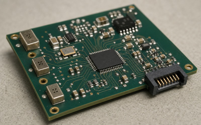
The PDM side is the place where layout discipline buys the greatest margin. The microphone signal starts at a small package, often near an enclosure opening or acoustic port. Long traces from that point to the conversion IC invite coupling from display lines, wireless sections, buck converters and motor drivers. A short PDM clock and data pair near the microphone and bridge keeps the high-rate one-bit stream inside a controlled zone. The I2S side can then travel toward the processor over a more ordinary digital audio route.
Short does not mean squeezed without thought. The microphone may need acoustic clearance, keepout near the sound port, shielding from airflow or mechanical vibration, and a clean reference plane under the digital traces. The bridge IC should sit close enough to avoid a long PDM run, while still allowing decoupling capacitors, clock parts and routing escapes to land without awkward stubs. If an alternate bridge or microphone is being considered, the package and pin escape pattern should be checked before the board outline is frozen.
Power Integrity Sets the Noise Floor
Digital audio parts still care about power. A bridge sitting between a microphone and a processor can pick up rail noise, clock noise and return-current mistakes even though the signal path is digital. Local bypass capacitors should be placed at the supply pins with a short return to the reference plane. If the microphone and bridge share a rail with wireless transmitters, LED drivers or switching regulators, the supply plan deserves another pass. A small part can become the place where the board tells on itself.
Power sequencing also deserves a check. If the microphone is powered while the bridge is held in reset, or if the bridge wakes before the host audio port is ready, the system may see invalid transitions. Those events are often harmless, but they can create pops, false wake events or capture errors in a voice product. A clean enable strategy, stable clock availability and known reset state are more useful than adding filtering after the capture path has already become unstable.
Clock Choices Decide the Real Interface Budget
Clocking is the part of the design that many schematics hide behind labels. A bridge can only produce a clean I2S stream if its clock relationships meet both the microphone and host requirements. The designer should review the source of the master clock, whether the bridge derives bit clock and frame clock internally or receives them, and how those clocks behave during low-power entry and wake. In a voice AI device, sleep and wake are often more demanding than continuous recording because the clock tree has to restart without creating a capture gap that the software mistakes for silence or noise.
The physical clock component also has placement consequences. An oscillator or crystal near the bridge should avoid power-inductor fields and fast display or memory traces. Its return path should not be forced around slots or connector cutouts. If the host is expected to provide the clock, the route from host to bridge should be treated as part of the audio timing path, not as spare digital routing. This is where a compact board can look correct in a schematic and still record unevenly in the lab.
Know What the Part Does Not Replace
A PDM-to-I2S bridge is not a full codec. It does not solve acoustic placement, microphone sensitivity matching, speaker feedback, array beamforming, or the analog output chain. Its job is narrower: take the digital microphone stream and present it in a format that the host audio block can consume. That narrow job is useful because it keeps a processor without a PDM input in the design, or it lets a team use a known microphone while avoiding a larger codec when output functions are handled elsewhere.
This boundary matters during substitution review. Replacing the bridge with a codec may add features but also brings new power rails, control registers, analog pins and layout zones. Replacing it with a processor that has native PDM may reduce parts but change firmware and clock ownership. The right choice depends on where the design already has audio capability and where it lacks one clean conversion step. Treat the bridge as a format and timing part, not as a general audio upgrade.
Review Package and Pin Escape Before Approval
The package is small enough that it can be underestimated. A bridge near a microphone and processor has to escape several timing lines, power pins and configuration pins in a small board area. The package pitch, pad style and pin order affect whether the microphone traces stay short or cross other signals. A substitute that looks similar in function may still force a new escape pattern, a different decoupling location or a longer clock route. Pin-compatible claims should be checked against the full layout, not against the symbol alone.
For purchasing and engineering review, the orderable suffix also matters. The suffix may identify tape and reel packaging, package option or temperature grade. Those details should match the assembly process and application environment. If an approved source list includes more than one bridge or microphone option, the board team should check whether each option keeps the same acoustic port position, supply needs, logic voltage and layout constraints. Audio capture quality can change because a small mechanical detail moved.
Place the Bridge in the Validation Plan
Validation should include more than a voice clip played back through a laptop. The board should be tested across the clock modes it will use, the supply states it will enter, and the interference sources that operate nearby. A useful test records silence, speech, wake words and high board activity while the processor, wireless section, display or motor control blocks run in realistic patterns. The audio file can then reveal dropouts, periodic tones, framing mistakes or edge cases that a short bench recording misses.
The bridge should also be checked during suspend and resume. If the product relies on always-on listening, the capture path must restart in a repeatable state. If it captures only during user interaction, the first frame after enable still matters. Firmware teams should log clock enable, DMA start, channel assignment and error flags during these events. Hardware teams should watch rail behavior and clock stability at the same time. Problems at this boundary are easier to fix before the layout is locked.
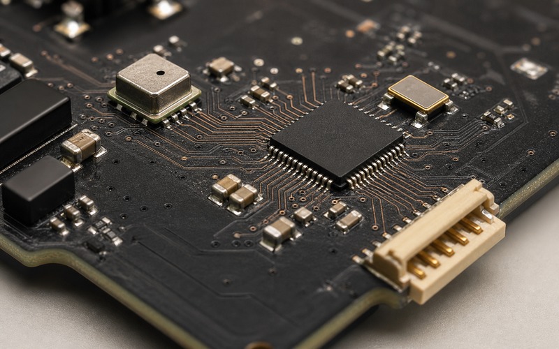
Separate Audio Routing From Noisy Board Areas
The bridge may be digital, but it belongs to the quiet side of the board. Keep it away from power inductors, motor phase nodes, antenna feedlines and high-current connector entries where possible. If the board is dense, use placement and return-path control to keep the PDM and clock routes from sharing the worst part of the layout. A clean boundary around the microphone, bridge and host audio entry is often enough to prevent the audio path from becoming a board-wide antenna for switching edges.
Mechanical design should be included in this review. The microphone opening, gasket, enclosure wall and board mounting can change the usable signal before the bridge ever sees a bitstream. If the bridge is moved to shorten the electrical route but the microphone is pushed into a poor acoustic location, the product gains little. Good audio capture comes from the joint decision: acoustic port, microphone package, PDM route, bridge placement, clocking, power and host interface all need to agree.
Use Substitution Review to Avoid Late Rework
Substitution should start with function, voltage and timing, then move to package, layout and firmware impact. A candidate bridge has to accept the intended PDM microphone, produce the host-side serial format, match the rail voltage and operate across the product temperature range. After that, the review should check the pinout, package land pattern, configuration method, startup behavior and any clocking differences. A second source that changes one of those items may still be usable, but it is not a drop-in decision.
For buyers, the safe request is an exact part number review with package suffix, approved alternatives and layout notes. For engineers, the safe approval path is to test the real microphone, bridge and host combination under the clocks and power modes that the final product will use. When those two reviews meet, the BOM decision becomes less fragile. The part is no longer a small black package between labels; it is a controlled timing and format boundary in the voice capture chain.
Final Component Selection Checklist
Before release, confirm the microphone output format, bridge input format, I2S frame settings, clock ownership, supply voltage, reset state, package option and pin escape. Check the acoustic port and microphone placement before optimizing only the schematic. Keep the PDM route short, place local decoupling close, avoid noisy board zones and verify that the edge-facing digital audio connector or host route follows a clean return path. Then record speech and silence under real board activity, including wake and low-power transitions.
If the design may need an alternate bridge, capture the conditions that made the first part acceptable: rail voltage, timing role, package, configuration, layout clearance, host compatibility and test result. That record helps sourcing teams evaluate alternates without turning each shortage or lifecycle change into a new audio experiment. A clean PDM-to-I2S path is a small section of the board, but it is the section that decides whether the voice model receives a stable signal or a problem that has already been baked into the hardware.