Free Shipping Over$200

- Products
- Marking
- Alternative

Keeping Motor Drive Noise Away From the AI Board
Keeping Motor Drive Noise Away From the AI Board
How to keep motor-drive switching noise away from an AI control board through partitioning, isolation, power design, cable routing, grounding, filtering and validation under real motion.
Start by naming the noise source
A motor drive is one of the loudest electrical neighbors an edge AI board can have. The drive switches current into an inductive load, charges and discharges MOSFET gates, moves current through phase cables, and often shares a compact enclosure with sensors, memory, wireless links and a processor. The AI side may be judging a camera frame, listening to a microphone array or running a control model, while the drive side is creating fast voltage edges and magnetic fields. The design has to admit that these two worlds want different conditions.
The first review is not a search for one magic isolator. It is a map of where noise is born, how it travels and what circuits are sensitive to it. The motor phase node, gate-drive loop, DC bus capacitor loop, current shunt, brake coil, encoder cable and motor cable can all inject disturbance. On the quiet side, the processor core rail, memory interface, clock source, camera or microphone input, reset line and communication ports may react to small disturbances. A useful design review puts those sources and victims on the same board drawing.
This is especially important when the motor drive and AI electronics are combined for size or cost. A robot joint controller, smart actuator, edge vision gimbal or compact mobile platform can work well with one controller board, but the board has to behave like two coordinated circuits. The power section is allowed to switch hard. The AI section is allowed to make small-signal decisions. The boundary between them decides whether those jobs can coexist.
Partition the board before adding parts
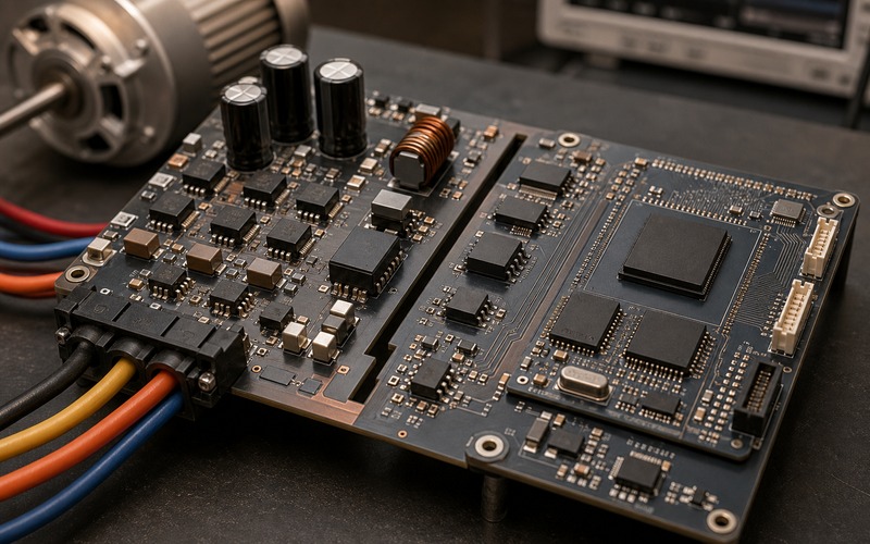
Physical partitioning should happen before the schematic is finished. Put the motor power stage, bus capacitors, shunts, gate drivers and motor connector in one area. Put the processor, memory, clock, camera or sensor connectors and low-noise regulators in another area. The two areas can communicate through defined crossings. They should not share random return paths, long parallel traces or copper pours that invite switching current to find its own route through the quiet side.
A visible keepout, slot, moat or clear boundary is useful because it forces the layout to make a decision. The boundary is not decoration. It defines where control signals cross, where isolated power crosses, where chassis or shield references connect, and where high-current copper stops. In a dense product, there may be no large distance available, but even a few millimeters of disciplined routing can be better than a mixed copper field where every signal passes near a phase node.
The board outline and connector positions matter. Motor phase wires should leave from the power section at the board edge, facing the cable path or motor housing. Camera, microphone, sensor, debug and host connectors should leave from the quiet side. If a motor cable has to cross over the processor or memory, the noise problem has already become mechanical. Good electrical design is helped by a mechanical layout that gives noisy cables a short and honest path out of the product.
Keep high-current loops small and local
Most motor-drive noise begins with loop area. The DC bus capacitor, MOSFET bridge, current shunt and phase output form fast current paths. When those loops are large, they radiate more and couple into nearby copper. When the bus capacitor is far from the half bridge, the board becomes part of the switching loop. When a shunt is placed without Kelvin routing, measurement and power current mix. When a gate driver return shares a path with logic ground, gate current can move the control reference.
The power section should be laid out as a compact energy path. Bus capacitors sit close to the bridge. Gate-drive loops stay short. Shunts have dedicated sense traces. Phase copper goes directly to the connector and leaves the board without weaving around quiet circuits. Thermal copper is useful, but it should not become an uncontrolled noise antenna. The goal is to give switching current a low-impedance local path so it has less reason to travel through the AI section.
Local does not mean careless. Copper width, thermal relief, current rating and creepage still need to be checked. A compact drive can be both thermally credible and electrically quiet if its high-current path is intentional. The danger comes from a layout that looks compact but forces return current through a distant plane or under sensitive traces. Review the current loop with the same seriousness as the bill of materials.
Choose isolation where the boundary must be real
Some signals can cross a noisy boundary directly after careful filtering and level translation. Others need galvanic isolation or a defined isolated domain. A digital isolator, optocoupler, isolated transceiver or isolated DC-DC converter is useful when the motor drive ground can move relative to the AI board, when common-mode noise is high, when a cable leaves the enclosure, or when safety and field wiring rules require separation. Isolation is a system choice, not a symbol placed between two nets.
The isolator has to match the signal. PWM, enable, fault, SPI, UART, encoder feedback and current-sense data each have different timing and direction needs. Propagation delay, channel skew, common-mode transient immunity, supply voltage, default output state and behavior during power sequencing all matter. A motor enable line that glitches during startup can be more dangerous than a noisy diagnostic line. The quiet side should know what the drive side will do when one supply is present and the other is not.
Isolation also creates a power question. The isolated side needs a supply that does not simply carry the same noise across the boundary. An isolated converter should be placed and filtered so that its switching current stays local. If the isolated supply is noisy, the design may move the problem rather than solve it. The boundary review should include both signals and power.
Filter crossings without hiding timing problems
Filtering helps when it is applied to a known path. Common-mode chokes, ferrite beads, RC input filters, small series resistors, TVS devices and feedthrough capacitors can reduce conducted and radiated disturbance. They should be placed at the boundary or at the connector where the noise enters or leaves. A filter placed far from the cable entry may allow the board trace itself to radiate or pick up noise before the filter does anything useful.
Filters also change signals. A reset line can tolerate more delay than a PWM edge. A fault line needs to be fast enough to protect hardware. An encoder or serial data line may fail if capacitance rounds the edge too far. A current-sense or analog feedback line can shift phase if the filter cutoff is chosen without the control loop in mind. The right filter is the one that meets both noise and timing requirements.
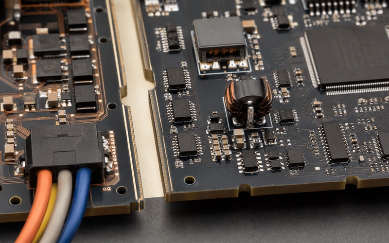
Every crossing should have a reason. A design with ten random ferrite beads is harder to debug than a design with three clearly justified filters. Name the crossing, the disturbance it is meant to block, the victim it protects, and the timing or voltage limit it must preserve. This makes later substitutions and layout changes easier to judge.
Give the AI side its own power integrity plan
Noise separation fails quickly when power rails are shared casually. The AI processor may have a core rail, memory rail, I/O rail, camera rail and analog or audio rail. These rails can react to motor load steps, battery sag, regenerative braking and ground bounce. The power tree should define which regulator feeds the drive logic, which regulator feeds the AI section, where bulk capacitance sits, and how load transients are prevented from moving the quiet rails.
A common mistake is to put one strong regulator in the middle and fan out to everything. That can work for small loads, but it creates a shared impedance path. A motor current step can move the input to the AI regulators. A processor current burst can enter the same bus that the gate driver uses. The better review separates noisy and quiet branches early, uses local regulation and filtering where needed, and keeps the return currents from sharing narrow copper.
Clock and reset circuits deserve special treatment. A motor event that creates a small rail dip may not damage the processor, but it can create a reset, clock jitter, memory error or camera frame fault. The design should check rail dip during motor start, hard braking, stall and fast direction changes. The AI side should remain deterministic while the drive side does the worst normal thing it is expected to do.
Route grounds as return paths, not as a slogan
Ground strategy is often described with broad labels, but the board only responds to copper and current. A single ground plane can work if high-current return paths stay local and sensitive signals do not cross the noisy region. Split grounds can work if every signal crossing has a defined return path. Either approach can fail when the return current is forced through a slot, connector shield, mounting screw or narrow bridge that was not part of the plan.
The review should follow each signal and its return. A PWM command crossing to the drive has a return path. An encoder signal returning to the AI side has a return path. A current-sense signal, fault line, isolated supply and shield connection each have return behavior. If a trace crosses a boundary while its return takes a different route, the loop area grows and noise coupling increases.
Chassis and cable shields add another layer. A motor cable shield, encoder shield or metal housing may need a termination point that controls high-frequency current without creating a low-frequency ground loop. The right answer depends on product class, enclosure, cable length and compliance target. The key is that the shield connection should be designed, not discovered during testing.
Protect external cables at the edge
Motor cables, brake lines, encoders, limit switches and remote sensors can carry noise into or out of the product. Any cable that leaves the board should be treated as an antenna and an entry point. Protection and filtering belong near the connector. The connector should face outward, the cable should leave without crossing the AI processor area, and the first protection parts should sit before the signal travels across the board.
ESD, surge and inductive kick protection should be selected for the real cable and load. A small TVS device can protect a logic input, but a motor phase or brake coil needs a different energy path. Common-mode chokes and ferrites can help on signal cables, but their current rating, impedance curve and saturation behavior matter. Protection parts should not add enough capacitance or leakage to break the signal they protect.
Cable routing inside the enclosure is part of the same review. A clean PCB can still fail if the motor cable is tie-wrapped across a camera flex, microphone input or RF antenna. The drawing should show cable exits, bend radius, shield termination and distance from quiet connectors. If the cable path is not controlled, the layout is only half reviewed.
Validate while the motor is doing real work
A quiet bench reading is not proof. The motor must run through the motions that create the noise: startup, acceleration, regenerative braking, stall tests, direction changes, high PWM duty, low battery or low bus voltage, and the maximum cable length expected in the product. The AI workload should run at the same time. If the product uses a camera, microphone, wireless link or sensor fusion, those functions should be active while the drive is switching.
Measure more than one node. Watch AI rail ripple, reset line behavior, clock stability, communication errors, sensor data quality, camera frame errors, audio noise, processor exceptions and motor fault signals. Use an oscilloscope for the fast edges and firmware logs for rare events. A design can look clean for seconds and still fail once per hour because a motor event aligns with memory access or sensor sampling.
The validation record should state the motor, cable length, supply voltage, PWM frequency, load, enclosure condition and AI workload used in the test. That record becomes the baseline when a motor, cable, isolator, converter, connector or board layout changes later. Without it, the team has no reliable way to decide whether a substitution has changed the noise margin.
Final design review checklist
Before the design is released, confirm the noisy power section, quiet AI section and all boundary crossings on the real layout. Check motor connector direction, cable exit, DC bus loop, gate-drive loop, shunt routing, isolator placement, isolated power placement, filter location, protection parts and return paths. Confirm that the AI processor, memory, clock, camera, microphone and sensor lines do not sit inside the motor-drive current path.
The final record should name the approved isolators, filter values, protection parts, regulators, cable shield terminations and layout constraints. It should also state the tested bus voltage, load, cable length, PWM frequency, enclosure condition and AI workload. Approved alternatives should be checked against delay, common-mode transient immunity, isolation rating, power noise, package, layout and lifecycle status before purchasing.
Good noise separation is not a single component. It is the result of partitioning, short power loops, defined crossings, credible isolation, quiet rails, controlled returns, protected cable edges and testing under real motion. When those items are reviewed together, the motor drive can switch hard while the AI board keeps making stable decisions.