Free Shipping Over$200

- Products
- Marking
- Alternative

INA240 for Phase Current Sensing in Motor Control
INA240 for Phase Current Sensing in Motor Control
How to review an INA240 class current-sense amplifier for phase-current measurement in motor control through shunt choice, PWM rejection, common-mode range, layout, timing and substitution risk.
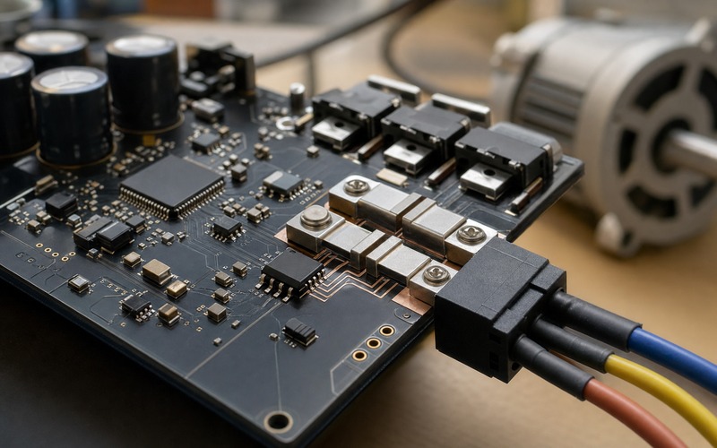
Start with the current the control loop must know
A motor-control loop needs a trustworthy view of phase current before it can control torque, protect the power stage or detect a stalled load. The controller can have a fast processor, a capable gate driver and strong MOSFETs, but the loop becomes guesswork when the measured current is noisy, delayed or offset from the real winding current. An INA240 class current-sense amplifier is often considered in this part of the board because it is built to read a small shunt voltage while large common-mode steps and PWM edges are moving around it.
The first review should define what the current signal is meant to do. A low-cost speed controller, a field-oriented servo drive, a robot joint, a pump, a fan and a small actuator all need different accuracy, bandwidth, common-mode margin and fault behavior. Some systems need only average current for protection. Others need phase current at a precise point in the PWM cycle. The current-sense amplifier should therefore be selected against the control algorithm and the power stage, rather than approved as a loose analog part.
Engineers and buyers should also agree on the boundary of the function. The part is part of a measurement path that includes the shunt resistor, copper layout, input filter, amplifier gain, ADC input range, sampling instant and firmware interpretation. A substitute that keeps the same package may still change offset, gain error, PWM rejection, output swing or recovery from input overdrive. The selection record should describe the whole current-measurement path.
Choose where the shunt belongs in the phase path
The shunt position decides what the amplifier sees. Low-side current sensing can be simple because the common-mode voltage is close to ground, but it may disturb the ground reference and may not show every phase condition. Inline phase sensing gives direct winding-current information and is attractive for field-oriented control, but it exposes the amplifier input to fast common-mode transitions near the switching bridge. High-side sensing can protect the supply path, but it may be less direct for phase-current reconstruction.
An INA240 class device is useful where the shunt sees switching common-mode movement, yet the topology must still be reviewed carefully. The controller should state whether it uses one, two or three shunts, whether reconstruction is needed, and whether the current sample is taken during a quiet part of the PWM period. The mechanical layout of the power stage also matters. A shunt tucked into a narrow copper path or placed far from the amplifier may satisfy a schematic and fail the measurement.
Before the part number is frozen, draw the real current path. Show the battery or bus input, MOSFETs, phase connector, motor cable, shunt, return path and sense traces. This drawing helps the team see whether the amplifier is measuring motor current, switch current, bus current or a mixture that changes with switching state. Current sensing is a circuit function, not a symbol beside a resistor.
Size the shunt before choosing gain
The shunt resistor sets the signal that the amplifier must recover. A larger shunt gives a larger sense voltage and improves signal-to-noise ratio, but it wastes power, heats the board and changes the copper temperature nearby. A smaller shunt reduces loss and heating, but it asks the amplifier and ADC to resolve smaller changes. The correct value comes from phase current range, peak current, fault current, acceptable dissipation, ADC range and control-loop resolution.
The calculation should include continuous current, short peaks, motor startup, braking and fault conditions. A shunt that looks fine at rated current can become a hot spot during repeated acceleration. A shunt that survives the current may still shift value enough with temperature to change torque estimation. Package size, temperature coefficient, pulse rating, solder-joint heat path and copper area should be part of the review. The amplifier gain is chosen after the shunt signal and dissipation are credible.
Output swing also sets a boundary. The amplifier must keep the expected positive and negative current signal inside the ADC input range after gain, offset and transient margin are included. If the design uses bidirectional current measurement around a mid-supply reference, that reference must be quiet and available before the ADC samples. If the output saturates during a normal current transient, recovery time can matter as much as gain accuracy.
Check common-mode voltage and PWM edge behavior
Motor-drive current sensing rarely sees a quiet analog input. The shunt can sit in a path where the common-mode voltage jumps with the half bridge, diode conduction and cable inductance. PWM edges can create sharp transients that look far larger and faster than the current signal of interest. INA240 class amplifiers are chosen partly because they are designed for strong PWM rejection, but the part still has absolute ratings, common-mode limits, input filtering needs and recovery behavior that must be respected.
The review should compare the real phase node voltage and switching speed against the amplifier data. Include bus voltage tolerance, regenerative events, ringing, negative transients and the worst case when the motor cable is attached. A prototype running at a low bench voltage may hide a problem that appears at the final bus voltage or after layout changes reduce damping. The amplifier input pins should never be treated as a place to absorb power-stage abuse.
PWM rejection is also a timing issue. The controller should know when the output is settled enough to sample. Sampling too close to a switching edge can turn a good analog layout into a noisy digital value. If the firmware changes PWM frequency, dead time, modulation method or sample phase, the analog front end may need to be checked again. Good phase-current sensing is a coordination between silicon, copper and firmware timing.
Route Kelvin sense lines as a measurement pair
The current path through the shunt carries motor current. The measurement path from the shunt to the amplifier input should carry almost no current. Kelvin routing keeps those two jobs separate by taking the sense pair from the correct pads of the shunt rather than from a convenient copper pour nearby. If the sense traces pick up voltage drop from the power copper, the amplifier reports board layout error as motor current.
Route the input pair short, close and symmetrical. Keep it away from switching nodes, gate-drive loops, bootstrap traces and motor phase copper. Place any input filter components near the amplifier pins and keep the filter balanced so it does not convert common-mode disturbance into differential error. A small resistor-capacitor filter can help with high-frequency noise, but too much filtering adds delay and can distort fast current changes.
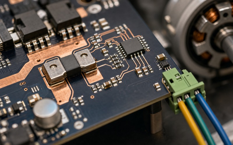
The ground and reference path deserve the same care. The amplifier output, reference pin and ADC input should share a clean measurement reference. A ground pour that also carries gate-driver return, bus-capacitor current or motor current can move the measured value. The layout review should follow both the force current path and the sense current path until the ADC conversion point.
Keep the amplifier away from noisy copper
Placement is a practical gate. The current-sense amplifier should be close enough to the shunt that the Kelvin traces remain short, but far enough from hot copper, switching devices and connector stress that the signal and solder joints stay stable. A board-edge motor connector is useful for wiring, but the phase conductors can radiate noise and pull mechanically on the board. The amplifier should not be trapped under a cable bend or placed in the hottest corner of the power stage.
Thermal gradients can create small but important errors. The shunt heats with current, the MOSFETs heat with switching loss, and the board copper spreads that heat unevenly. Offset drift, shunt resistance change and local reference movement can all enter the measured current. The thermal review should include continuous load, short overload, enclosure airflow and the heat path into mounting hardware. A current signal that is accurate on an open bench may shift inside a compact product.
Input protection should be reviewed without adding a new accuracy problem. Series resistors, clamps, common-mode chokes or filter capacitors can protect or quiet the input path, but they can also add leakage, imbalance, phase delay or recovery issues. Every added part should have a reason tied to the actual motor-drive environment. The final layout should look like a measurement instrument placed inside a power converter, not a fragile analog trace crossing a switching field.
Match bandwidth to the control algorithm
Bandwidth should follow the control task. A protection circuit may tolerate a slower current value if it only needs to stop sustained overload. A torque-control loop or field-oriented controller needs a current value that follows the phase current with predictable delay. Too little bandwidth hides real current ripple and delays the loop. Too much bandwidth can pass switching residue into the ADC and force the firmware to fight noise.
The review should include amplifier bandwidth, filter cutoff, ADC sampling rate, digital filtering and PWM timing as one path. If the ADC samples once per PWM cycle, the analog output needs to settle by that sampling instant. If the system uses two-shunt reconstruction, missing or noisy samples can create angle-dependent error. If the motor has low inductance, the current ripple can be high enough that average and instantaneous current are different design quantities.
Firmware should expose measurement health during bring-up. Log raw ADC counts, calculated current, offset at zero current, current during locked-rotor tests and current during fast speed changes. Compare those values with an external probe or a calibrated load when possible. The target is not a perfect waveform on a bench. The target is a measured current signal that the controller can trust while the real motor is switching and moving.
Bring up current sensing before closing the loop
Current sensing should be checked in stages. Start with the board unpowered from the motor bus and confirm amplifier supply, reference and output offset. Then apply a known current through the shunt if the hardware allows it. After that, run the power stage at low bus voltage, then increase voltage and load while watching the current signal. Closing a torque or position loop before the measurement path is understood can hide a wiring or polarity error until the motor moves unexpectedly.
Polarity is a common bring-up issue. The sign of the measured current must match the phase convention used by the control algorithm. A swapped Kelvin pair, reversed shunt direction, inverted ADC scaling or firmware sign error can make a stable-looking sensor signal push the controller in the wrong direction. The bring-up record should state the phase naming, current direction, ADC scaling, reference voltage and zero-current calibration method.
Fault behavior also belongs in bring-up. Check what happens when the current exceeds the normal range, when the output rails, when the motor cable is unplugged, when a phase is shorted during a controlled test fixture, or when the bus voltage sags. The controller should not treat an impossible current value as a valid torque command. Measurement failure should be easier to diagnose than a damaged power stage.
Review substitutions before purchasing
A current-sense amplifier alternate should be reviewed against the real motor-control environment. Pin-compatible does not mean behavior-compatible. Compare input common-mode range, PWM rejection, gain options, offset, gain error, bandwidth, slew behavior, output swing, reference behavior, supply range, package thermal behavior and input protection. A small change in delay or output recovery can matter when the controller samples at a fixed point in the PWM cycle.
The shunt and layout may also limit substitution. If the alternate needs a different gain, the shunt value or ADC range may need to change. If it has different input bias behavior, the filter network may shift the result. If it tolerates less common-mode stress, the same half-bridge layout may no longer be safe. Purchasing should receive an approved alternate list with the conditions that were actually checked, rather than a list based only on package and headline gain.
Lifecycle and sourcing reviews should stay tied to engineering risk. The exact package, temperature grade, qualification level and assembly format should match the approved board. If a second source is required, prove it on the same shunt, PWM frequency, bus voltage, motor cable and firmware timing. That keeps a supply decision from becoming a late motion-control problem.
Final component selection checklist
Before an INA240 class current-sense amplifier is released for motor control, confirm the current-sensing role, shunt location, maximum continuous current, peak current, fault current, shunt value, shunt package and shunt temperature rise. Check the amplifier gain, common-mode range, PWM rejection, bandwidth, output swing, reference plan and ADC input range. Review Kelvin routing, input filter balance, decoupling, ground reference, thermal placement and connector direction.
The final record should include the tested bus voltage, PWM frequency, motor load, sample timing, zero-current offset, current polarity, calibration method and fault response. It should also show how the measured signal behaves during startup, braking, load steps and high-current operation. Keep the approved shunt, amplifier, filter values and ADC scaling together in the same decision record.
A reliable phase-current measurement path gives the control loop a stable view of torque and protects the power stage from guesswork. Treat the amplifier as one element in that path. When the shunt, copper, amplifier, ADC and firmware timing are reviewed together, the selected part has a clear reason to stay on the board and any alternate has a clear test it must pass.