TLV320AIC3204 for Multi Input Capture on a Voice Front End
A single microphone can prove that a voice product hears sound, but it rarely proves that the final front end can survive the real enclosure, user distance and noise field. A TLV320AIC3204 class codec becomes useful when a design needs several analog inputs, controlled gain, a host audio link and a clean path from acoustic openings into digital samples. The part is selected as a capture boundary. It has to accept microphone signals, bias and filter them, convert them with enough headroom, hand the data to the processor and keep the power and clock behavior stable through wake and mute states.
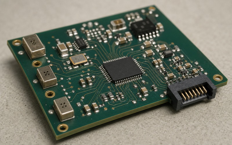
Start With the Capture Geometry
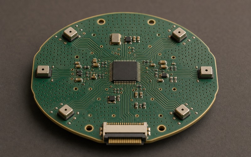
Multi input voice capture begins in the enclosure rather than in the register table. The board may need microphones on different edges, a front and side pickup pattern, a reference input, or an auxiliary analog source. Those positions decide cable length, port shape, gasket pressure and exposure to vibration. The codec should be reviewed after the mechanical team identifies where sound enters the product. If all microphones are moved later to fit the industrial design, the electrical plan can change even when the schematic symbol stays the same.
Each input path should have a defined job. One input may carry near speech, another may face the room, and another may serve as a reference or line source. If the product only needs one clean microphone, a simpler codec or bridge may be enough. If the product must compare several acoustic positions, the codec has to support the needed input count, gain range, bias options, routing and host interface without forcing awkward external multiplexing.
Map Every Microphone Input Before Routing
The schematic should name every input by physical role, not by pin label alone. A pin called input one means little during layout review. A pin called front microphone, side microphone or reference input tells the reviewer what noise, cable movement and acoustic condition to expect. The input map should include signal type, bias source, expected level, coupling capacitor, filter parts and any protection part near an external entry point.
This map also helps sourcing. A microphone change can alter sensitivity, output impedance, bias current or package height. A codec input that worked with one microphone may need a new gain setting or different filter values when the microphone changes. Good documentation keeps microphone, filter and codec decisions tied together, so a purchasing substitution does not quietly become an audio redesign.
Set Gain for Headroom and Noise
Input gain should be chosen from acoustic conditions. Far speech, close speech, wind, button clicks, enclosure taps and speaker leakage can all reach the front end. A high gain setting can help quiet speech but can clip loud events. A low gain setting protects headroom but can expose noise after digital processing. The TLV320AIC3204 class of codec gives the designer control, but that control has to be tied to measured signals from the product shape.
The right check is a set of raw recordings. Capture silence, normal speech, loud speech, far speech and device activity before applying speech enhancement. Record each input channel separately and together. If one channel clips while another stays clean, the gain plan may need per-channel adjustment. If all channels carry the same power noise, the layout or supply plan needs attention before software tries to hide the problem.
Keep Bias and Filtering Close to the Inputs
Microphone bias is part of the signal path. It should be quiet, filtered and routed with a short return path. The bias network and input filter should sit close to the codec input or microphone entry, depending on which side needs the greatest protection from noise pickup. Long unfiltered analog traces invite coupling from display lines, switching regulators, wireless bursts and digital audio clocks.
Input filters should match the microphone and sampling plan. Oversized capacitors can slow settling after wake. Weak filtering can pass switching noise into the ADC. Series resistance, coupling capacitance and shunt capacitance should be checked against input impedance and desired bandwidth. A voice front end does not need every ultrasonic detail, but it does need stable speech content and controlled out-of-band energy.
Plan the Host Audio Format Early
The codec can carry several input channels only if the host can receive them in the selected serial format. I2S, TDM or related serial modes have to match the processor port, DMA setup and software pipeline. The review should identify word length, sample rate, frame length, clock master, channel order and what happens when fewer channels are active. A board can record silence or swapped channels when the format is assumed rather than verified.
Firmware should own a repeatable initialization order. Power rails, clock, reset, control bus, input route, gain, ADC enable and host port start should happen in a known sequence. During wake, the sequence can matter more than steady operation. If the host starts recording before the codec settles, the first frames can contain pops, clipped samples or channel alignment errors.
Treat Clocking as an Audio Constraint
Clocking sets the frame for every captured sample. A codec that shares a noisy clock route with a processor, display or wireless section can inject timing uncertainty into the audio path. The clock source, divider settings and serial interface timing should be reviewed with the same care as the analog input network. If the product changes sample rate between modes, each rate must be tested with the same microphone geometry.
Physical clock placement matters as well. A local oscillator or crystal should sit near the codec with a clear return path. If the processor supplies the master clock, the route should avoid power inductors, antenna feedlines and high current connector areas. Sleep and wake states deserve special attention because voice products often spend more time entering and leaving low power modes than they spend recording continuously.
Separate Analog Inputs From Output and Power Noise
A multi input front end creates more analog routing than a single microphone design. Several traces may approach the codec from different edges, and each one can pick up noise. Keep these routes away from speaker current, motor drive, LED switching, wireless transmit paths and power conversion nodes. When crossing is unavoidable, maintain a controlled reference plane and avoid long parallel runs with noisy nets.
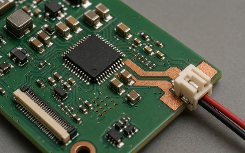
The digital audio connector should face outward or toward the processor zone without forcing analog inputs to loop around it. Board-edge connectors, microphone ports and FFC exits should match the real assembly direction. A clean input layout is both electrical and mechanical: the signal route, cable direction, acoustic port and enclosure clearance all need to agree.
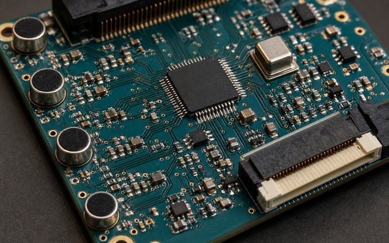
Check Power Rails and Sequencing
The codec may need analog, digital and I/O rails with different noise and sequencing requirements. The analog rail deserves low noise and local decoupling. The digital rail must support interface activity. The I/O rail has to match the host logic level. If one rail comes up late or collapses during sleep, the codec may lose register state or present an invalid signal to the host.
Power state validation should include microphone bias enable, ADC start, channel route changes and low power exit. Measure rail behavior while recording, not during an idle bench state. If a nearby regulator changes mode during capture, listen for tonal artifacts and inspect raw samples. A voice front end can pass a steady state test and fail when the product begins using its normal power policy.
Validate the Control Bus and Register Set
A flexible codec depends on control registers. Input selection, gain, bias, ADC path, clocking, digital audio mode, power state and mute behavior all come from the control bus. The register set should be versioned with the hardware revision. If the team changes microphones, rail voltage, clock source or host mode, the register setup should be reviewed again.
During validation, log every codec write around startup and wake. Compare the log with recorded audio events. If a channel appears late, if gain changes between boots, or if one input has a different noise floor, the control sequence may be part of the cause. Hardware and firmware should share this evidence before the BOM is frozen.
Production test planning should use the same channel map. A short fixture can inject a known tone, pink noise or calibrated speech sample into each input position, then compare channel level, polarity, noise floor and sample alignment. This does not replace acoustic testing in the enclosure, but it catches assembly faults, wrong component values, damaged microphone bias paths and swapped channels before the board reaches final product test. A multi input codec gives useful diagnostic access when the test plan keeps each input identifiable from pad to recorded file.
Review Package, Pinout and Assembly Risk
Multi input capture can put pressure on the package even when the part is small. Several analog pins, supply pins, clock pins and digital interface pins need short routes and local parts. Pin escape should be checked before the board outline is fixed. A substitute with the same broad function may move analog pins to another side, require a different exposed pad, or change the location of decoupling parts.
Assembly review should cover package pitch, paste control, inspection access and any nearby acoustic structure. Microphone cans, gaskets and sound ports can limit rework access. A connector or FFC placed for assembly can also change input routing. The component choice should be checked against the physical build process and the electrical design together.
Use Substitution Review With Real Signals
An alternate codec must be checked against real product signals. Function count is only the first screen. The review should compare input channels, bias options, ADC performance, gain steps, noise, digital audio modes, clocking, control interface, power rails, package and firmware changes. A part that looks close in a catalog can create a different channel order, gain law or wake behavior.
The safest review keeps raw audio samples, register settings, layout notes and microphone details together. Buyers can request exact part number support and approved alternates, while engineers can test each candidate against the same capture files and operating modes. This avoids approving a substitute that passes a pin count check but fails the acoustic product.
Final Component Selection Checklist
Before release, confirm microphone positions, input count, bias plan, filter values, gain range, ADC headroom, serial audio format, clock ownership, power rails, package and connector direction. Record all input channels during silence, near speech, far speech, enclosure taps, wireless activity and low power transitions. Check the raw files before judging processed audio.
If the TLV320AIC3204 class codec remains the selected part, document the exact orderable part, register setup, microphone assumptions, filter values, layout limits and alternate review path. The value of the codec is the controlled path from several acoustic openings to repeatable digital audio that the voice processor can trust.