Free Shipping Over$200

- Products
- Marking
- Alternative

AS5047P for Magnetic Angle Feedback on a Servo Motor
AS5047P for Magnetic Angle Feedback on a Servo Motor
How to review an AS5047P class magnetic angle sensor for servo motor feedback through magnet alignment, air gap, signal interface, speed, noise and substitution risk.
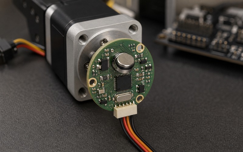
Start with the feedback problem, not the sensor part number
A servo motor loop is only as useful as the angle information fed back into it. The motor, gear train, load and controller can all look capable on paper, but the loop becomes unstable or inaccurate when the feedback device reports the wrong position, misses fast motion, adds timing jitter or drifts when the assembly warms up. An AS5047P class magnetic angle sensor is a useful option because it can read the angle of a rotating diametric magnet without a sliding contact, optical disk or exposed encoder slot. The review still has to start from the servo requirement, not from the sensor name.
The first question is what the control loop must know. A joint that holds position after a move, a motor that follows a fast profile, a small actuator that needs commutation feedback, and a shaft that only reports a user knob position all place different demands on resolution, update rate, latency, absolute position after power-up and noise. The same magnetic sensor can be a good fit in one of those designs and a poor fit in another if the magnet, air gap, mounting stack or digital interface is wrong. Treat the sensor, magnet and mechanical stack as one feedback component.
Place the magnet before judging the electronics
Magnetic angle sensing depends on the field that reaches the sensor die. A strong integrated circuit cannot rescue a poorly placed magnet. The magnet should be centered on the rotation axis, magnetized in the correct direction, held at the specified distance from the sensor and kept flat enough that tilt does not become an angle error. In a servo motor, those conditions depend on the shaft end, bearing stack, retaining hardware, PCB standoff, cover thickness and assembly tolerance. The magnet location is therefore a mechanical design decision as much as an electrical one.
Prototype reviews often miss this point because a hand-held magnet and a loose PCB can produce changing angle numbers on the bench. Production needs a defined magnet grade, diameter, thickness, magnetization direction, adhesive or holder, axial tolerance, radial offset, tilt limit and air gap range. The review should include how the magnet will be installed, how it will be inspected and what happens if the motor shaft has end play. A feedback sensor should be approved after the magnet stack is defined, not while the magnet is still an informal bench part.
Control air gap, centering and runout
Air gap is the distance between the magnet and the sensing plane. Too much gap weakens the field and reduces margin. Too little gap can create mechanical risk, saturation risk or assembly interference. Centering errors and shaft runout add periodic angle error because the sensor sees the magnet move off axis as the motor rotates. A servo loop may hide some error at low speed, but the error can return as torque ripple, audible noise, poor settling or a position offset at the load.
The board should be designed around a realistic stack tolerance. PCB thickness, solder joint height, sensor package height, adhesive thickness, magnet holder height and motor face tolerance all add up. If the assembly has a cover or bracket, that part must keep the air gap stable rather than pushing the encoder board. The validation should include minimum and maximum gap builds, not a single best-case prototype. The right drawing shows the motor face, shaft, magnet, sensor package, PCB and connector together.
Choose the signal interface by the controller, not by habit
AS5047P class devices can provide digital angle information through a fast serial interface and may also support incremental or pulse-width style outputs depending on configuration. The best choice depends on what the controller needs and how the firmware is structured. A field-oriented motor controller may need fast, low-latency angle samples. A position servo may need absolute angle after power-up. A host processor may need a robust diagnostic path more than a high sample rate.
The interface review should cover voltage levels, timing, cable length, connector pinout, pull resistors, signal integrity and error detection. If the sensor board is mounted on the motor and the controller sits on another board, the cable becomes part of the interface. Routing a high-speed signal beside motor phases or switching power traces can turn a clean sensor into an intermittent feedback problem. The controller should also define how it handles parity errors, missing frames, index alignment and startup calibration.
Check speed, latency and control-loop timing
Angle sensors are often compared by resolution first, but a servo loop also cares about timing. The controller uses the measured angle to decide current, torque or position correction. If the angle data arrives late, arrives at uneven intervals or is filtered too aggressively, the loop may feel soft or unstable. High rotational speed adds another constraint because the angle changes during the sample, transfer and computation path. The required speed range should be checked against sensor update behavior, interface timing and firmware scheduling.
The timing review should include the full loop: sensor sampling, data transfer, controller interrupt, algorithm execution, PWM update and motor response. A part can have enough nominal resolution and still fail the motion requirement if the data path is too slow. Conversely, a lower effective resolution may be acceptable when the loop timing is clean and the mechanical system has enough reduction. The design should state the expected maximum shaft speed, sample timing, allowed delay and how angle wraparound is handled.
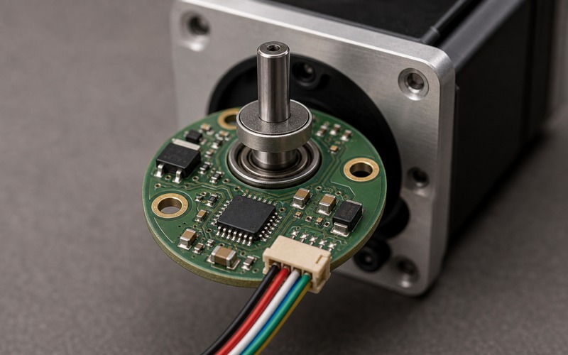
Give the sensor a quiet electrical environment
A magnetic encoder board can sit very close to a motor, power stage, brake coil or cable bundle. That location is mechanically convenient and electrically noisy. The sensor supply should have local decoupling, a clean return path and a regulator or filter strategy that matches the rest of the motor controller. The digital lines should avoid motor phase currents and switching nodes. If the encoder cable leaves the motor housing, its connector and shield or ground strategy should be reviewed with the whole drive.
Noise problems often appear as rare position jumps rather than a permanent failure. A single bad angle sample can make a servo kick, buzz or fault. The validation should run the motor at load while reading the sensor, not read the sensor with the power stage idle. Test startup, braking, high current, low battery or low rail voltage, and fast direction changes. Watch for angle discontinuities, communication errors and position-control corrections that repeat at the PWM or motor electrical frequency.
Keep the encoder board serviceable and buildable
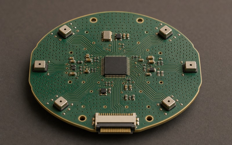
The board shape and connector direction matter. A round or compact encoder board usually mounts at the motor end, so the signal connector should leave outward toward the cable path or enclosure channel. A connector that points into the shaft, bracket or motor body creates bending stress and assembly mistakes. Mounting holes should leave enough copper clearance, and the sensor should remain centered after screw torque, adhesive cure and cable strain are applied.
Test access also matters. During bring-up, the team may need to probe supply, ground, serial clock, data, chip select, index or diagnostic pins. If all pads are hidden under the motor or connector, feedback debugging becomes slow. The board does not need to expose a large debug header in the final product, but the prototype should give engineers a clean way to compare raw angle data with motor motion, alignment marks and controller state.
Review calibration and zero position
Absolute angle feedback still needs a zero convention. The sensor may report a repeatable electrical angle, but the product needs to know where mechanical zero is. In a servo motor, zero may be tied to a shaft flat, a gearbox position, a robot joint, a valve stop or a factory alignment mark. The design should define when zero is written, how it is stored, how it is checked after assembly and how the controller behaves if the value is missing or inconsistent.
Calibration should be kept practical. If the assembly needs a fixture, the fixture should align the shaft and magnet under realistic torque and temperature conditions. If the product performs a homing routine, the routine should account for backlash or end-stop compliance. If an alternate sensor or magnet is proposed later, the calibration method should still work. A feedback part is ready for production only when the electrical angle and mechanical reference have a repeatable relationship.
Compare alternatives as a magnet-and-system change
An AS5047P class sensor can sometimes be replaced by another magnetic encoder, but the change is larger than a pinout comparison. Candidate parts may differ in magnet strength requirements, package height, air gap range, interface timing, diagnostic bits, output format, startup behavior and error handling. A part with the same general function may need a different magnet or a different PCB height to reach the same accuracy.
The alternate review should compare the whole feedback stack. Check whether the existing magnet remains acceptable, whether the sensor can tolerate the same axial and radial error, whether the controller interface and timing still match, and whether the calibration record remains valid. If the alternate changes magnet position, board mounting or firmware interpretation, it should be treated as an engineering change. That protects the servo loop from a substitution that looks simple in purchasing but changes motion behavior.
Final component selection checklist
Before an AS5047P class magnetic angle sensor is released for a servo motor, confirm the feedback role, required speed, latency, resolution and startup behavior. Define the magnet material, size, magnetization direction, holder, centering tolerance and air gap range. Check the PCB stack, sensor package height, connector direction, local decoupling, signal routing and controller interface. Run the motor under load while monitoring angle data, communication errors, temperature and loop behavior.
The final record should name the exact sensor, magnet, motor interface board, connector, controller interface, calibration method and approved alternatives. It should also state the tested gap range, maximum shaft speed, electrical noise conditions and zero-position method. That record gives engineering and purchasing a clear boundary. The sensor is not being chosen as a loose IC. It is being chosen as a complete angle-feedback path that the servo loop can trust.
The checklist should also state what was measured on the final mechanical stack rather than on a loose bench setup. Record the raw angle stability at rest, the angle error during slow rotation, any communication errors during loaded motion, and the temperature range used for the test. Those measurements make later changes easier to judge because the team can compare a new magnet holder, board revision or alternate sensor against the same baseline.