Free Shipping Over$200

- Products
- Marking
- Alternative

TB6612FNG for DC Motor Drive in a Small Robot
TB6612FNG for DC Motor Drive in a Small Robot
How to review a TB6612FNG class dual DC motor driver for a small robot through motor current, PWM control, braking behavior, connector direction, board layout and substitution risk.
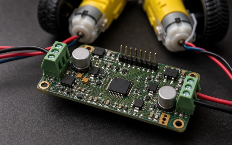
Start with what the robot drive has to do
A small robot makes a DC motor driver look like a commodity part until the wheels touch the floor. The board has to start both motors from rest, steer at low speed, reverse without upsetting the processor, survive a stalled wheel, and keep motor noise away from sensors and radios. A TB6612FNG class device can be a practical choice for that level of robot because it combines two H-bridge channels, logic-level control, PWM speed control and braking modes in a compact package. The useful review is not whether the part is popular. The useful review is whether the driver, motor, connector and board layout can handle the real mechanical load.
The selection should start from the robot behavior, not from the driver headline current. A light line follower, a toy-scale rover, a tabletop service robot and a small inspection platform can all use two brushed DC gearmotors, yet their electrical stress is different. One product may spend most of its time creeping under closed-loop control. Another may bump into fixtures, stop hard, and restart from a high-friction surface. The driver must be reviewed against motor stall current, startup current, duty cycle, PWM frequency, braking behavior, battery voltage range, connector placement and the thermal space around the board.
Separate motor choice from driver choice
The motor is the load that sets the driver problem. Gear ratio, wheel diameter, gearbox friction and robot mass decide how much current the motor asks for during acceleration. The rated no-load current is a poor sizing number because the robot rarely runs with the wheels free in the air. The stall current or a measured startup current is usually closer to the stress that the H-bridge and connector must survive. If the motor vendor provides only voltage, speed and torque, the prototype should measure current during startup, turn-in-place and blocked-wheel conditions before the driver is frozen.
A TB6612FNG class driver may be able to run a small gearmotor well, but it should not be asked to hide a poor motor choice. If the robot needs more torque, changing the gearbox or wheel may reduce driver heat more effectively than choosing a larger H-bridge. If the robot needs finer low-speed control, an encoder and control loop may help more than raising PWM frequency. The driver review therefore records the exact motor, supply range, wheel load, measured startup current and intended control method before the part is treated as approved.
Size the H-bridge around stall and startup current
DC motor current rises quickly when the rotor is not moving. That is why the moment after a command starts can be harder on the driver than the steady motion that follows. The H-bridge current rating, package temperature, motor connector rating and copper width should all be checked against the startup case. A small robot can also stall one wheel against a cable, carpet edge or wall while the other wheel keeps turning. The driver should either survive that short event or the controller should detect it quickly enough to reduce current.
Datasheet current numbers need context. Peak current, continuous current and thermal shutdown are not interchangeable design limits. The board may have less copper than the evaluation board used for the rating, and the robot enclosure may have less airflow than an open bench. A good review asks how long the motor can draw high current, where the heat leaves the package, how the battery voltage changes under load, and whether the firmware has a current or timeout strategy. The answer often decides whether the TB6612FNG class part is suitable or whether a driver with current regulation and stronger protection is needed.
Keep PWM, braking and direction logic explicit
TB6612FNG class drivers usually give the controller separate inputs for direction, standby and PWM. Those pins make the part flexible, but they also make firmware behavior part of component selection. Coast, short brake and reverse commands feel different at the wheels. A robot that coasts smoothly may stop late; a robot that brakes aggressively may draw more current and disturb the battery rail. The desired behavior should be written before the board is released, especially if the robot has to dock, align with a charger, follow a narrow path or stop near a person.
PWM frequency is another practical decision. A low frequency may create audible noise and rough low-speed motion. A very high frequency can increase switching loss and make layout noise harder to manage. The chosen frequency should match motor response, driver limits, firmware timing and the rest of the electronics on the board. Direction changes should also be sequenced carefully. Reversing a spinning motor can create a current surge, so firmware should include a controlled stop or dead-time strategy when the mechanical system needs it.
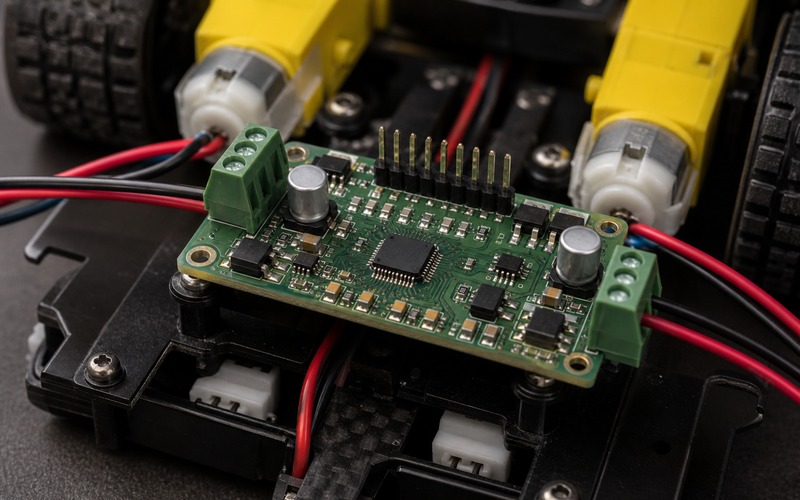
Give the driver copper, decoupling and a real return path
The layout around a dual motor driver decides whether the part behaves like a clean control device or a noise source. Motor current should move through short, wide paths from the supply input, through the H-bridge, out to the motor connector and back through a defined return path. The battery or motor rail needs bulk capacitance close to the driver area, and each driver supply pin needs local ceramic decoupling. Long thin traces, shared return paths with sensors, and motor current that crosses under a radio or processor can create intermittent problems that are difficult to debug later.
Thermal layout matters even when the robot is small. A compact package still needs copper area, thermal vias when the footprint supports them, and distance from heat-sensitive parts. If the driver sits beside a battery charger, wireless module or image sensor connector, the product may pass a short drive test and fail after heat soak. The board should be reviewed with the robot closed, motors loaded and the battery at the voltage range that creates the worst combination of current and heat. That test gives a better answer than touching the driver after a short bench run.
Put motor connectors on the board edge
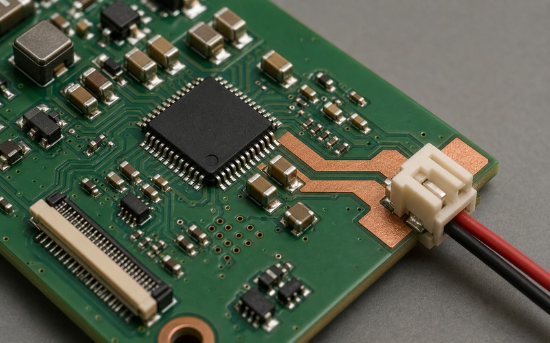
Motor connectors are mechanical parts as much as electrical parts. They should sit on the board edge with the cable leaving outward toward the motor, harness channel or robot chassis wall. A connector that points inward forces tight bends across the PCB, makes assembly harder, and can push motor wires over logic traces or sensor connectors. For a small robot, that routing mistake can also place the cable where a wheel, gearbox or chassis cover can rub it. The connection direction should be checked with the real enclosure and the real gearmotor position.
Pin order needs equal attention. The two wires of each motor should stay as a pair from connector to motor. If the left and right motor outputs are swapped, the robot can drive opposite to the firmware convention. If one motor pair is reversed, the robot may spin when it should move forward. Clear assembly drawings, keyed connectors where possible and a simple bring-up test reduce the risk. Any approved alternate connector should keep the same pin spacing, latch direction, current rating and cable exit path, rather than matching only the number of pins.
Check noise near sensors, radios and processors
A robot controller often shares a small board with an IMU, camera connector, microphone, wireless module, edge processor or battery gauge. The DC motor driver is one of the loudest circuits on that board. Motor brushes create electrical noise, PWM edges create switching current, and long motor leads can radiate. The layout should keep motor loops away from sensitive inputs, and the harness should leave the board without crossing high-impedance analog or antenna areas. Filtering at the motor or connector may be needed when the robot carries precision sensors.
Ground strategy should be reviewed with current paths in mind. A clean schematic ground symbol does not guarantee clean measurement if motor return current passes through the same copper used by sensor references. Star points, planes, local decoupling and connector placement all matter. The test should include the robot driving while the sensors are sampled and the radio is active. Watch for IMU spikes, camera frame errors, wireless dropouts, processor resets and battery gauge jumps. These symptoms often point back to motor current paths rather than to the sensor or processor itself.
Bring up the drive on the real robot
The first test should use the actual battery, motors, cables and chassis. Start with a current-limited bench supply or a protected battery path, wheels off the ground, and firmware that can disable both channels quickly. Confirm standby behavior, direction mapping and PWM response before the robot touches the floor. Then test one motor at a time, both motors together, turn-in-place, low-speed creep, fast start, braking and reverse. Each step checks a different stress point in the driver choice.
After the basic movement works, repeat the test with the wheels on the intended surface. Carpet, rubber, floor gaps and payload weight can change current dramatically. A robot that looks fine on a stand can overheat on the floor. Measure driver temperature, motor temperature and battery dip during repeated starts and stalls. If the design uses closed-loop speed control, test the loop during low battery and partial stall conditions. The driver should be accepted after those real operating cases, not after a free-spinning motor test alone.
Review substitutions before purchasing
A dual DC motor driver is easy to substitute on paper and risky to substitute in a robot. Candidate parts can differ in pinout, standby polarity, input logic thresholds, output resistance, peak current rating, package thermal path, braking behavior, fault reporting and protection strategy. A replacement may also require different decoupling or a different ground layout. Even when the package appears close, the robot behavior can change because motor control is both electrical and mechanical.
A useful alternate-part review compares the exact robot requirement against the exact candidate. Check whether both motors can start under load, whether braking and coast modes match firmware, whether the driver stays cool in the enclosure, whether connector routing remains correct, and whether the part has the same behavior at low battery. Procurement can then hold approved options without turning an availability change into an untested redesign. If an alternate changes firmware behavior or board layout, it should be treated as an engineering change rather than a simple purchasing swap.
Final component selection checklist
Before a TB6612FNG class driver is released for a small robot, confirm the motor and gearbox choice, measure startup and blocked-wheel current, compare those numbers with the driver and connector limits, choose PWM frequency and braking behavior, verify standby and direction logic, give the H-bridge short copper paths and local decoupling, place motor connectors on the board edge, and test sensor and radio behavior while the motors run. The checklist should include the real enclosure because thermal and cable routing errors often appear only after the board is installed.
The final record should name the exact motor, supply range, driver package, connector, board revision, firmware mode and approved alternates. It should also state the conditions used for thermal and stall testing. That record helps engineers keep the robot motion predictable, and it helps buyers avoid substitutions that look harmless until the wheels start moving. A small robot does not need an oversized motor driver by default. It needs a driver selected against the current, heat, layout, connector and control behavior it will face in the product.