Free Shipping Over$200

- Products
- Marking
- Alternative

DRV8825 Driving a Stepper on a Motion Stage
DRV8825 Driving a Stepper on a Motion Stage
How to review a DRV8825 class stepper driver for a motion stage through phase current, current-limit setting, thermal layout, motor wiring and substitution risk.
Start with the motion the stage has to make
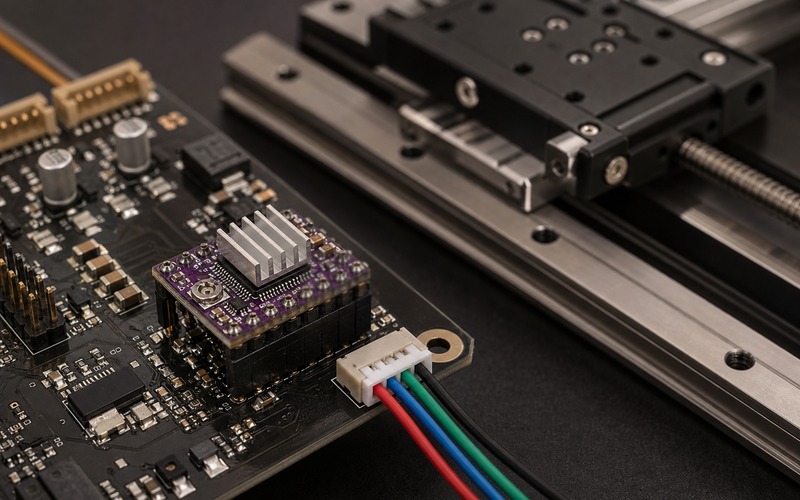
A motion stage makes a stepper driver look simpler than it is. The load moves in one axis, the controller sends step pulses, and the motor follows a screw, belt or rail. The hard part sits between those plain facts. The axis may need to creep through a camera focus routine, stop without ringing at an inspection point, reverse direction without losing position, and hold a load while the frame vibrates. A DRV8825 class driver can be a practical part for that job when the current, heat, wiring and control timing are reviewed as one system.
The part should not be selected from motor voltage alone. A bench prototype often runs at low speed with generous air around the board. A production motion stage may sit inside a compact enclosure, close to a camera, a lamp, a processor board and a cable bundle. The same driver that looks calm on the bench can run hot when the carriage dwells at one position, when the step rate changes quickly, or when the board loses copper area to mechanical holes. Selection starts by writing the axis requirement in board terms: phase current, supply range, step rate, hold current, connector position, airflow, expected duty cycle and the space available for the driver package or plug-in carrier.
Match phase current to real torque demand
A stepper motor is usually described by holding torque, rated phase current, winding resistance and inductance. Those numbers need to be translated into the torque that the stage needs after friction, screw pitch, belt reduction and acceleration are included. The DRV8825 setting should leave enough current for the worst move, yet it should avoid using heat as a hidden safety margin. If the carriage has to hold position for long periods, hold current can become the thermal design point rather than the fast move current.
Current limit is therefore a design value, not a knob to turn until the motor feels strong. The sense resistor value, reference voltage range and current-limit equation should be checked from the exact board or module. Two carrier boards can place the same driver family beside different sense resistors and copper areas. A replacement carrier that appears pin compatible can change the real current limit at the same trim setting. The review should record the target phase current, how it was measured, where the probe was placed, and whether the limit remains stable after the board warms up.
Choose supply voltage for speed without abusing heat
A higher motor supply can help a stepper winding reach current faster, which matters when the stage moves at speed. That does not mean the highest possible rail is the right choice. The driver still dissipates heat, the motor cable still radiates switching edges, and the board still has to survive supply transients when the axis decelerates. The useful question is whether the chosen rail lets the motor reach the commanded current at the required step rate while staying inside the thermal and electrical limits of the driver, capacitors, connector and cable.
Many failures around a compact motion stage come from treating the motor rail as a separate problem from the logic rail and the rest of the electronics. A camera, sensor or microcontroller on the same product may be sensitive to ground bounce and cable noise. Bulk capacitance near the motor input, local ceramic capacitors at the driver, a clear return path and a sane cable route reduce the amount of motor energy that leaks into the measurement chain. If the motor rail is shared with other loads, the startup and stall cases deserve the same attention as normal jogging.
Set microstepping and current decay for usable motion
Microstepping is often sold as a smoothness feature. On a motion stage it is also a control and resonance feature. Fine steps can reduce visible vibration and acoustic noise, but they do not multiply absolute positioning accuracy by the same ratio. Mechanical backlash, screw pitch error, belt stretch, friction and load changes still decide repeatability. The chosen step mode should match the controller pulse rate, firmware timing and the real resolution needed by the application.
Current decay behavior affects the current waveform in the coils and can change low-speed smoothness, mid-band resonance and heat. A driver setting that feels quiet during a short hand test may behave differently during a long scan, a high acceleration move or a repeated home routine. The board review should include the mode pins or configuration network, the default state at reset and the way firmware enters the intended operating mode. A floating mode pin or a weak pull resistor can turn a production board into a lot-to-lot motion problem.
Give the driver a real thermal path
The DRV8825 family is often seen on small plug-in carriers with a heatsink, and that can hide the real thermal question. The heatsink helps only when it contacts the package correctly and when heat can move from the package into copper, air and the surrounding mechanical structure. A tall carrier mounted above a base board may leave less airflow than the bench setup suggests. If the board sits next to a warm processor or inside a sealed motion head, the case temperature during a hold state can be the number that matters.
Thermal review should cover the copper under the driver, the via pattern, nearby heat sources, connector clearance, mounting height and airflow path. The stage should be tested with the worst realistic duty cycle: repeated moves, long holds, maximum ambient and the enclosure closed. If the driver enters thermal shutdown during that test, the issue is not solved by reducing the lab speed. The design needs a lower current, more copper, a better module position, a stronger driver, a cooler motor, or a change in the mechanical load.
Place motor wiring and connectors as part of the circuit
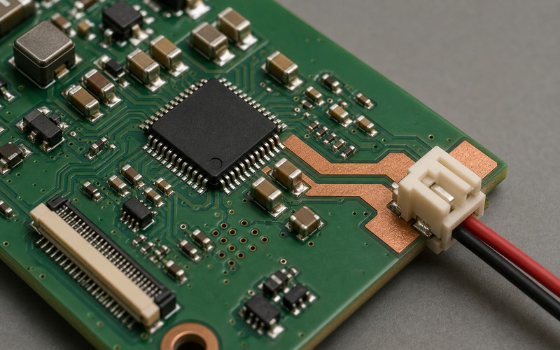
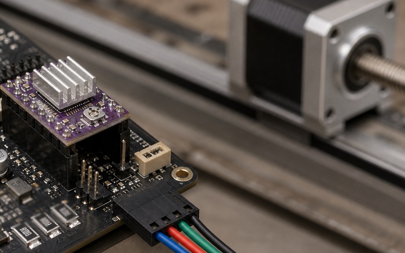
The motor connector belongs at the board edge with the cable leaving toward the motor or harness path. Pointing the connector inward may look harmless in a render, but it creates assembly stress, tight bends, and service mistakes in a real product. A motion stage also moves near metal rails, screws and brackets, so the cable exit direction should be checked against the whole mechanism. The connector latch, pin order, strain relief and cable bend radius need the same review as the electrical rating.
Phase order must be treated carefully. Swapping one coil pair can make the motor shake instead of move; reversing a pair can change direction; crossing motor leads through a noisy path can inject switching current into a sensor cable. The board should mark coil groups in the assembly drawing, and firmware should have a defined direction convention. If the design allows an alternate driver board, the connector pinout, enable polarity, fault behavior and current-limit components should be compared before it is approved.
Check logic timing, faults and controller interface
A stepper driver is easy to command, but the STEP, DIR, ENABLE and fault lines still need electrical review. Logic voltage, input thresholds, pull resistors and reset state should match the microcontroller or motion controller. Direction setup time before the next step pulse matters when firmware changes direction at high speed. Enable behavior matters when the product wakes from sleep, homes the stage, or recovers from an error.
Fault outputs should not be left as decorative pins. Overcurrent, thermal shutdown, undervoltage and a loose motor connector can all look like missed steps if the controller ignores driver status. A motion product should decide what happens when a fault appears: stop the axis, reduce current, retry after cooldown, ask for service, or log the event. The right answer depends on whether the stage is moving a camera, a dispenser, a lock, a scanner or a small robot fixture. The part selection review should include that behavior before the board enters production.
Review substitutions before buying parts
A DRV8825 class driver may be replaced by another stepper driver or by another carrier board, but the change is rarely a pure purchasing decision. The package, pinout, current rating, sense resistor value, current decay mode, microstep table, thermal pad, fault behavior and protection features can all shift. Even a board sold for the same socket can place the trim pot differently, use another resistor value or expose a different connector height.
A useful substitution note compares the exact axis requirement against the exact candidate part. It should ask whether the motor current can be set to the same measured value, whether the motion profile stays stable, whether thermal rise stays acceptable, whether the connector direction still fits the assembly, and whether firmware needs a mode or polarity change. Buyers and engineers can then discuss approved alternates without turning a sourcing decision into an untested motion redesign.
Bring up the driver on the actual axis
The first power-up should be done with the real stage, the real cable and a current-limited supply. Start with the carriage free to move, the current set below the intended value, and the controller ready to disable the driver if the axis stalls. Then increase current in measured steps, watch motor temperature and driver temperature, and listen for rough current regulation at low speed. This process often exposes a coil pair error, a loose connector, a reversed direction convention, or a current-limit setting that looked correct before the motor cable was connected.
After the basic move works, run the moves that the product will actually use. Homing, slow scan, fast reposition, long hold and repeated direction changes each stress a different part of the driver choice. The test should record missed-step symptoms, audible resonance, supply dips, fault events and heat soak. If an alternate driver or carrier is proposed later, it should repeat this same bring-up path rather than being accepted from a pinout comparison alone.
Final component selection checklist
Before a DRV8825 class driver is released for a motion stage, check the motor phase current against torque and duty cycle, confirm the supply rail against speed and transient margin, measure the current limit on the actual board, verify microstep and current decay settings, run the thermal test in the real enclosure, confirm connector orientation and phase pinout, and test firmware handling of enable, direction and fault lines. Then review any alternate carrier or driver against those same conditions.
The result should be a short engineering record rather than a vague preference for a familiar driver. It should say which motor, which rail, which current setting, which board version, which heatsink or copper option, which connector and which approved alternatives were checked. That record gives procurement a clear part boundary, and it gives the design team a better chance that the motion stage shipped to customers behaves like the one that passed on the bench.