TMC2209 for Quiet Stepper Drive in a Robot Joint
How to review a TMC2209 stepper driver for a robot joint through phase current, microstepping, thermal layout, motor wiring, supply margin and substitution risk.
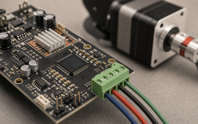
A robot joint asks more from a stepper driver than a desktop test rig does. The motor may move slowly while carrying load, hold position while the frame vibrates, reverse direction near a limit and sit close to sensors or microphones that expose every current ripple. TMC2209 is attractive in this setting because it fits compact boards and supports quiet stepper operation, but the part only works well when current, thermal path, motor wiring and firmware settings are reviewed as one motion axis.
The driver is not a magic silencer. Noise can come from current waveform, motor resonance, supply ripple, loose mechanics, cable routing or control timing. A quiet driver mode can reduce audible harshness, yet it cannot hide a motor running above its torque margin or a joint with poor alignment. Selection has to start with the joint load and then move back to the driver, not the other way around.
The approval question is practical: can this driver move the chosen motor at the required speed, hold torque and duty cycle while staying inside temperature, supply and acoustic limits? If the answer is yes, document the current setting, sense resistor value, board copper, motor connector, firmware mode and accepted substitutes.
Start From Joint Torque and Speed
A robot joint turns a torque requirement into a motor phase-current requirement. Gear ratio, arm length, friction, acceleration and holding load decide how much current the motor needs. A driver choice that looks fine from peak current alone can fail if the joint spends long periods holding load or moving in small increments.
Stepper motors can lose torque as speed rises. A joint that only needs slow positioning may care more about holding current and heat. A joint that moves a camera head or small gripper may care about mid-speed smoothness and vibration. The driver review should name the speed range that matters to the mechanism.
Do not approve the driver from motor label current alone. Many motors list rated current for a winding at a thermal condition that does not match a small robot joint. The driver current limit, supply voltage, motor resistance, inductance and duty cycle all shape the real operating point.
A useful test moves the actual joint through its load profile. It should include holding, low-speed creep, acceleration, direction reversal and stop conditions. Bench spinning a free motor confirms wiring, but it does not prove the joint has torque margin.
Current Limit Is a Design Value
TMC2209 current setting depends on the sense resistor, configuration and driver mode. The value should be chosen from motor load, coil heating, board thermal path and acoustic result. Too little current loses steps. Too much current heats the motor and driver, and it can make the joint louder.
The approval file should record RMS current, peak current interpretation, sense resistor value and the firmware setting used to reach it. If the board has an adjustable current setting, the production value needs a lock or a test step. A small change at this point can turn a quiet joint into a hot joint.
Current also changes with supply voltage and motion profile. A higher supply can improve current rise at speed, but it raises stress on the power path and driver. A lower supply can reduce heat but lose torque at speed. The correct setting is tied to the joint duty cycle.
Measure motor case temperature and driver temperature during the movement pattern that matters. A static hold test catches one failure. A repeated motion test catches another. The driver has to pass both if the product uses both.
Microstepping Helps Smoothness, Not Torque Budget
Microstepping can make low-speed motion smoother and reduce visible vibration. It divides the commanded movement into smaller current steps, so the joint can move with less harsh stepping behavior. That is useful for camera heads, small arms, valves, sliders and robot joints near acoustic sensors.
Microstepping does not create extra torque margin. At small step increments, mechanical friction, gearbox play and motor detent effects can still dominate. The motion may look smooth in command space while the joint moves in tiny stick-slip jumps.
The review should match microstep setting to the controller pulse rate and required speed. Fine microsteps require more step pulses for the same shaft speed. If the controller cannot generate clean timing, the driver may receive jitter that becomes acoustic noise or uneven motion.
Interpolation can help the motor sound smoother, but firmware still needs a clean acceleration profile. A stepper axis that jumps from rest to high pulse rate can sing, buzz or lose position regardless of driver choice.
Quiet Mode Has Operating Boundaries
Quiet stepper operation comes from current shaping and motion profile. It works best where the motor speed, supply voltage and load stay inside a suitable region. At higher speed or load, the driver may need a different current control style to preserve torque and avoid missed steps.
A robot joint should be tested in the mode that will ship. If the firmware changes between quiet movement, high-torque movement and hold current, the transitions need validation. A joint that is quiet during slow motion but clicks during mode change can still fail an acoustic target.
The acoustic check should use the final motor, gearbox, frame and enclosure. A bare motor can sound acceptable while the assembled joint amplifies a narrow frequency. Cables, covers and mounting screws can also change the sound.
Record the mode, supply, current and acceleration settings with the sound test. Without those values, a later firmware or motor substitution can erase the result.
Thermal Layout Decides Sustained Motion
A compact stepper driver board can pass a short move and fail a long hold. Driver heat depends on current, supply, switching behavior, copper area, airflow, enclosure and nearby parts. A small heatsink helps only when it connects to a useful thermal path and fits the mechanical stack.
The board should give the driver copper, vias and local airflow where possible. Sense resistors and supply capacitors also need space. A hot regulator or radio module next to the driver can reduce margin. Thermal review should include the whole board, not the driver package alone.
Holding current deserves separate review. Many robot joints spend long periods holding position. Reducing hold current can cut heat and noise, but it must leave enough margin against load, vibration and backdrive. The release setting should be measured, not guessed.
Thermal testing should include the highest expected ambient condition, repeated motion and hold. Record driver board temperature, motor case temperature and any thermal shutdown or current reduction behavior.
Motor Wiring and Connector Direction Matter
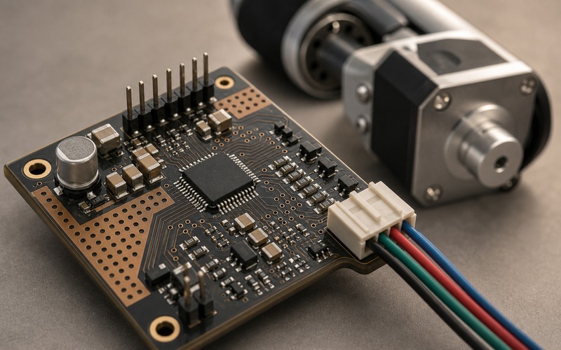
The motor phase connector is part of the motion system. Phase order, cable length, wire gauge, shield strategy and connector retention all affect reliability. A wrong phase pair can make the motor rough, weak or noisy before any firmware setting is considered.
For a robot joint, the connector should face the board edge or an accessible service direction. A connector that points inward can force sharp wire bends, strain the solder joints or interfere with the mechanical frame. That risk is easy to miss in a schematic review.
Keep motor phase traces short and practical, with enough copper for current and a return path that does not inject noise into logic or sensor references. Separate motor current loops from encoder, limit switch, microphone or analog sensor inputs when the board allows it.
A production check should verify phase pairing and connector orientation. If an alternate connector is approved, its latch, pitch, height and cable exit direction need the same review as the original.
Supply, Decoupling and Fault Handling
Stepper drivers draw pulsed current. The supply path needs bulk capacitance, local ceramic decoupling and a layout that keeps high-current loops compact. Weak supply layout can create audible noise, reset events or driver faults.
The VM supply capacitor should be close enough to support current changes. Logic supply and reference pins need clean decoupling. If the board shares supply with sensors, radio or a processor, motor current can become a system-level noise source.
Fault handling should be part of the firmware plan. Overtemperature, shorted output, undervoltage or open motor conditions should not leave a joint in an unsafe or confusing state. A quiet driver still needs visible diagnostics in production and service.
The test should include motor unplug, stalled joint, high load, low supply and warm board conditions. These tests show whether the driver, firmware and power path fail in a controlled way.
Firmware Configuration Belongs in the BOM Review
A TMC2209 design is partly hardware and partly configuration. UART settings, current limits, microstep mode, standstill current, motion ramp and fault reading can change the same board from smooth to noisy or from cool to hot.
The firmware configuration should be treated as part of the approved component setup. If the driver is sourced as a module, the module default settings may not match the final product. If the board is custom, the register setup and motion profile should be linked to the exact schematic values.
Do not let procurement approve a replacement board or driver module from package shape alone. The current-sense network, copper area, connector orientation and firmware access route must match the tested design. A quiet demo board is not proof that the production joint will behave the same way.
Store the validated settings next to the driver selection record. That makes later repair, second sourcing and firmware review much easier.
Substitution Review for a Quiet Axis
A substitute stepper driver can change current regulation behavior, sense resistor calculation, package heat path, pinout, fault reporting and configuration method. A drop-in footprint does not guarantee the same sound or torque.
A substitute motor can change resistance, inductance, detent torque, rotor inertia and resonance. A substitute connector can change cable strain and phase assignment. A substitute gearbox can change reflected load and noise. The joint must be reviewed as a system.
The approval file should divide replacements into three groups: safe with the same firmware and test, allowed after current and thermal retest, and blocked until motion and acoustic validation are repeated. This keeps purchasing options useful without hiding engineering risk.
When supply planning lists alternatives, include the validation scene: load, speed, current, supply, ambient temperature and acoustic target. That context prevents a replacement part from being approved only because it fits the board.
Release Checklist
Before release, run the final robot joint through the motion profile it will use in the product. Check start, stop, slow creep, reversal, hold, high load and fault cases. Measure motor temperature, driver temperature, supply ripple, position loss and audible noise in the final mechanical assembly.
Record the exact driver part, package, current-sense value, current limit, microstep setting, supply voltage, motor connector, motor phase order, board thermal features and firmware configuration. Keep the cover and service direction of the connector in the mechanical review.
A quiet stepper joint is the result of driver selection, current setting, motor choice, firmware timing, board layout and mechanical design working together. TMC2209 can be a good fit when those details are controlled. It becomes risky when the board treats it as a small driver IC that can be swapped or configured later without rechecking the joint.