 Free Shipping Over$200

- Products
- Marking
- Alternative

Measuring Position and Angle Without Contact
The contact is what fails. A potentiometer reads position by dragging a wiper across a resistive track, and every read wears the track a little more, until a dead spot opens up exactly where the mechanism spends its life resting. Contactless sensing removes the wiper and reads a field instead. Nothing touches, so nothing wears.
The catch does not disappear, it moves. A magnet that turns, a metal target that approaches, a liquid that rises past an electrode: each one couples to its sensor through geometry, and the geometry is now part of the measurement. A magnet glued half a millimetre off the shaft axis bends the angle reading. A coil mounted too far from its target loses signal it can never get back. A capacitive electrode with a careless ground return reads a level that is not there. The resolution printed on the datasheet is earned at the ideal alignment its maker measured it at, and the assembly line is where those bits are kept or lost. Pick the sensing principle by what the moving part is made of, then design the mounting like it is part of the circuit, because it is.
Reading an angle from a magnet
The rotating cases all work the same way. A small magnet, magnetized across its diameter rather than through its faces, sits on the end of the shaft. The chip beneath it samples the field direction with an array of sensing elements and computes the angle from the field components, so the answer is absolute from the moment power arrives, no index search, no counting from a home position. The magnet is a few millimetres of neodymium, and the diametric magnetization is non-negotiable: an ordinary axially magnetized disc presents the wrong field shape entirely. What separates the parts is resolution, interface, speed and how gracefully each one tolerates a magnet that sits a little off where the drawing says.
The AS5600 measures contactless magnetic rotary angle with twelve bits, four thousand and ninety-six positions around the circle, and it is built to be the drop-in heir to the potentiometer it replaces. It speaks I²C, and it can be told to put out a ratiometric analog voltage or PWM instead, so firmware written for a pot keeps working with the wiper gone. Start and stop angles can be programmed to map a partial mechanical swing onto the full output range, which is exactly the knob and gimbal use it sells into. An automatic gain stage reports whether the magnet sits too close or too far, a free health check on the one mechanical variable the chip cannot fix. Twelve bits put each step under a tenth of a degree, finer than the backlash of the gear train it usually sits behind, and a watchdog drops the part to low power when the magnet stops moving. The boards that carry it cost little and are everywhere, which has made it the default first magnetic encoder in small robotics.
The AS5048A measures absolute angle at high resolution, fourteen bits, sixteen thousand three hundred and eighty-four positions, around a fiftieth of a degree each. It reads out over SPI with PWM as the fallback, and the zero position burns into one-time-programmable memory, so a joint can be assembled in whatever orientation the mechanics prefer and zeroed in software afterward. The extra two bits over the AS5600 matter where the angle feeds a control loop rather than a display: a robot joint, a camera gimbal, an antenna positioner, places where the loop gain amplifies every count of sensor noise into visible dither. Two of them can daisy-chain on one SPI bus, readings clocking through in a single transaction, and the arctangent comes out of an internal CORDIC engine fed by the Hall array. It asks a little more of the magnet placement in return, since the finer the resolution, the sooner eccentricity shows up as a repeating error that sweeps around the circle once per turn.
The MA730 measures magnetic angle at high speed, and speed is the entire personality of the part. It keeps fourteen-bit resolution while the shaft spins at tens of thousands of revolutions per minute, and beside the SPI absolute readout it generates incremental quadrature outputs, the classic ABZ pulses, with a programmable count per revolution. That second interface is the point: a motor controller catches edges the instant they happen instead of polling a register and reading an angle that is already stale. Pulses per revolution program anywhere up to the full fourteen-bit count, and the index pulse lands at whatever angle it is told to, which lets the part impersonate the optical encoder a controller already expects. The filter window is adjustable in steps, trading angle noise against group delay, so the same part runs quiet on a slow axis and fast on a spinning one, with the short settings answering in tens of microseconds and letting the low bits dance for it. It is the choice when the angle is feeding commutation rather than a user interface.
The TLE5012B gives a motor precise angle feedback, and it senses the field differently: giant magnetoresistance rather than Hall plates, reading the field direction with elements whose resistance depends on the angle between current and magnetization. It calibrates itself as it runs, tracking the gain and offset drift of its bridges over temperature against parameters stored at final test, so the fifteen-bit angle emerges already corrected rather than waiting for the host to clean it up. It ships in pre-configured variants whose secondary interface is already set up for the job, incremental pulses, PWM, or Hall-switch emulation that lets it stand in for three discrete commutation sensors, which means the firmware team inherits a working interface instead of configuring one. The synchronous serial interface delivers the absolute angle on demand, and every reading travels with status bits that flag a weak field or an internal fault, the kind of bookkeeping a safety reviewer asks for by name. It is an automotive-qualified part from Infineon and it shows: the datasheet reads like a safety document, and the part is happiest bolted to a motor that must not lie about where its rotor is.
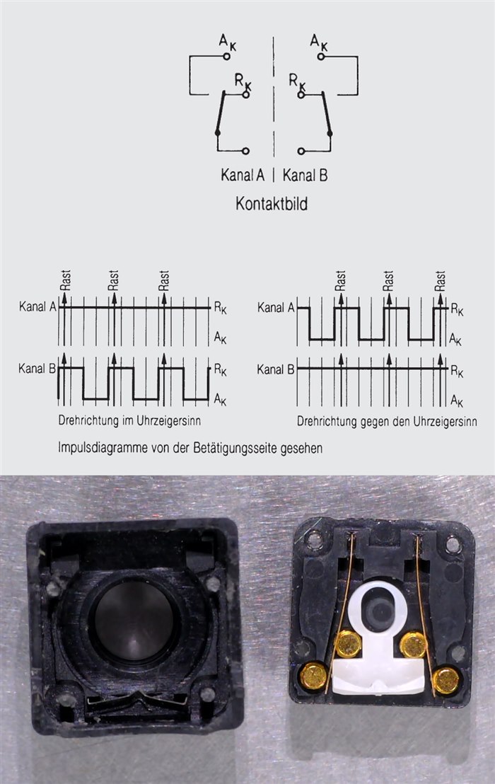
What a spinning shaft does to the numbers
A shaft that turns fast turns the angle into a moving target, and the sensor's answer is always a little old. The chip needs time to sample the field, filter the result, compute the angle and clock it out an interface, and those delays add into a propagation time that converts directly into angle error: at ten thousand revolutions per minute the shaft sweeps sixty degrees every millisecond, so a hundred microseconds of total latency means the controller acts on an angle six degrees stale. In a field-oriented motor loop that error lands in the torque vector, and the motor pays for it in heat and lost output. Filtering sits in the same trade. A narrow filter leaves the low bits dancing with noise, a wide one steadies them and eats bandwidth the control loop wanted, and the right setting depends on the axis, which is why the better parts make it programmable. The interface is the third leg. Polling an absolute register over a serial bus costs tens of microseconds per read and the answer ages while it travels; incremental edges arrive the moment the angle crosses a boundary and cost nothing to parse, which is why the high-speed parts bother to generate them. None of this shows up on a bench where the shaft is stopped, and all of it decides whether the motor sings or stutters at speed. The static resolution war between twelve and fourteen bits is settled in marketing material; the dynamic one is settled in microseconds, and it is the one the motor feels.
At speed the spec that matters is measured in microseconds, not bits.
Position without rotation
Not every position is an angle. A button cap that flexes a tenth of a millimetre, a valve spool sliding in its bore, coolant climbing a tank wall: these are displacements, and two more field types cover them. A coil driven as part of a resonant circuit sees its inductance drop when a conductive target approaches, because the target hosts eddy currents that push back on the field, and the resonant frequency climbs in response, so measuring frequency measures distance. An electrode pair sees its capacitance shift when anything with a different dielectric constant enters the space between them, liquid, a fingertip, a moving plate, and femtofarads of change carry the position. The resonances sit in the hundreds of kilohertz to a few megahertz, set by the coil and the capacitor beside it.
The LDC1614 measures inductive proximity and displacement by reading that resonant frequency to twenty-eight bits across four channels, which turns a spiral of copper traced on the PCB itself into a precision position sensor with a parts cost of nothing. The target only has to be conductive: a steel bracket, an aluminium flag on a mechanism, the metal dome under a sealed button. Oil, dust, ink and any non-conductive grime between coil and target change the reading not at all, which is why inductive sensing owns the dirty end of industrial position measurement. Sub-micron motion resolves at close range, and a second coil wired as a reference channel cancels the temperature drift the first one cannot avoid, since copper resistance walks with heat whether the target moves or not. The channels convert in turn through a shared core, and the steadiness of the reference clock decides how many of the twenty-eight bits hold information rather than jitter. The design work moves out of the BOM and into the layout, where coil diameter sets the sensing range and the ground pour underneath must keep its distance.
The FDC1004 measures capacitive position and level across four channels with femtofarad resolution inside a fifteen-picofarad window, and its shield drivers are the feature that makes it usable outside a lab. An actively driven shield electrode surrounds the sense electrode at the same potential, so the parasitic capacitance to everything behind the sensor drops out and the sensing lobe points where the layout aims it. The signature trick is liquid level through a plastic tank wall: copper strips on a flex outside the tank, water's high dielectric constant doing the signalling inside, no port, no float, no seal to fail. Each channel measures against the shield or differentially against a second electrode, and an offset register pulls the standing capacitance of the assembly out of the window, so the span spends itself on signal instead of on the cable. For the tank, a reference electrode kept low enough to stay submerged cancels what temperature does to the liquid's dielectric constant. It serves proximity wake-up the same way, a hand approaching a panel shifting picofarads before it touches anything, and the sample rate of a few hundred hertz is generous for a level that changes by the minute.
Choosing between the two is mainly a question about the target. A conductive moving part in a dirty place wants the coil; a liquid, a human hand or a non-conductive part wants the electrode. The failure modes swap the same way: inductive sensing shrugs at grime and resents nearby structural metal, capacitive sensing sees through plastic and resents conductive films, condensation and careless grounding. Condensation is the cruel case, a film of breath on the inside of a panel reading as a phantom touch until it dries. The honest answer is sometimes both, an inductive button under a capacitive wake-up surface, each covering the other's blind spot.
The mounting is the real datasheet
Every part above quotes its precision at a geometry it does not control. The magnet parts want the magnet centred on the rotation axis within a fraction of a millimetre and floating at the height the gain stage approves of; eccentricity draws a once-per-revolution error wave through the angle that no amount of resolution removes. The coil wants its target inside roughly one coil diameter, since sensitivity falls off steeply with distance and a target parked too far away leaves only noise. The electrode wants its field lines landing on the thing being measured, and every centimetre of unshielded trace adds parasitic capacitance that buries the femtofarads carrying the signal. Calibration can absorb the repeatable part of a bad mounting, a fixed offset, a known curve. It cannot absorb the part that varies from unit to unit on the line, which is why the tolerance drawing decides the production yield long before firmware gets a say. The gain indicator on the magnet parts exists for exactly this, a pass-fail number a test fixture reads out in a second per unit.
The selection, then, runs backward from the mechanics. A rotating shaft with a magnet on its end takes the AS5600 when the job is a knob, the AS5048A when a control loop needs the counts, the MA730 when the shaft spins fast enough to make latency the enemy, the TLE5012B when the motor is the product and the angle must survive automotive scrutiny. A sliding or flexing conductive part takes the coil and the LDC1614; a liquid or an approaching hand takes the electrode and the FDC1004. All of them are cheap enough that proving two principles on the prototype costs less than a week spent arguing about it.
The wiper wore out because it touched. These parts last because they measure from a distance, and the price of that distance is paid in millimetres of alignment, held for the life of the product.






